background image


Pa

ge

18


5.


FAQ – Trouble shooting Interface functions 


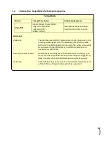
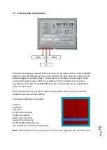
For any troubles which may occur, check the following table for a solution before requesting 

support from your vendor.


Symptom 

Reason 

Possible solution 

No picture/black 

picture (factory 

picture). 

Not all connectors have been 

reconnected to factory head-

unit or monitor after 

installation. 

Connect missing connectors. 

No power on CAN-bus box (all 

LED CAN-bus box are off). 

Check power supply of CAN-bus box. Check CAN-bus 

connection of CAN-bus box. 

CAN-bus box connected to 

CAN-bus in wrong place. 

Refer to the manual where to connected to the CAN-

bus. If not mentioned, try another place to connect to 

the CAN-bus. 

No power on video-interface 

(all LED video-interface are 

off). 

Check whether CAN-bus box de12V ACC on red 

wire output of 8pin to 6pin cable. If not cut wire and 

supply ACC +12V directly to video-interface. 

No picture/black 

picture/white picture 

(inserted picture) but 

factory picture is OK. 

No picture from video source.  Check on other monitor whether video source is OK. 
No video-source connected to 

the selected interface input. 

Check settings dips 1 to 3 of video interface which 

inputs are activated and switch to corresponding 

input(s). 

LVDS cables plugged in wrong 

place. 

Double-check whether order of LVDS cables is exactly 

connected according to manual. Plugging into head-

unit does not work when the manual says to plug into 

monitor and vice versa. 

Wrong monitor settings of 

video-interface. 

Try different combinations of dips 7 and 8 of video-

interface. Unplug 6pin power after each change. 

Inserted picture totally 

wrong size or position. 

Inserted picture double 

or 4 times on monitor. 

Inserted picture 

distorted, flickering or 

running vertically. 

Video sources output set to 

AUTO or MULTI which causes 

a conflict with the interfaces 

auto detection. 

Set video source output fixed to PAL or NTSC. It is best 

to set all video sources to the same standard. 

If error occurs only after 

source switching: Connected 

sources are not set to the 

same TV standard. 

Set all video sources to the same standard. 

Some interfaces can only 

handle NTSC input. 

Check manual whether there is a limitation to NTSC 

mentioned. If yes, set source fixed to NTSC output. 

Inserted picture b/w. 

Inserted picture qual. 

bad. 

Picture settings have not been 

adjusted. 

Use the 3 buttons and the interface's OSD to adjust the 

picture settings for the corresponding video input. 

Inserted picture size 

slightly wrong. 

Inserted picture 

position wrong. 
Camera input picture 

flickers. 

Camera is being tested under 

fluorescent light which shines 

directly into the camera. 

Test camera under natural light outside the garage. 

Camera input picture is 

bluish. 

Protection sticker not 

removed from camera lens. 

Remove protection sticker from lens. 


Содержание 27-590

Страница 1: ...tures Video inserter for factory infotainment systems 2 CVBS video inputs for after market devices e g DVD Player DVB T tuner FBAS Rear view camera video input Automatic switching to rear view camera...

Страница 2: ...box 2 Installation 2 1 Place of installation 2 2 Connection schema 2 3 Connecting 10pin PNP cable 2 4 Connection picture signal cable 2 5 Connection video sources 2 5 1 After market rear view camera 2...

Страница 3: ...Changes updates of the vehicle s software can cause malfunctions of the interface We offer free software updates for our interfaces for one year after purchase To receive a free update the interface m...

Страница 4: ...or a FM modulator can be used If 2 audio sources shall be connected to the infotainment an additional electronic is necessary to switch them Factory rear view camera Automatically switching back from...

Страница 5: ...deo interface Some settings must be selected by the dip switches on the video interface Dip position down is ON and position up is OFF After each Dip switch change a power reset of the Can box has to...

Страница 6: ...hen Head Unit variieren Daher ist es notwendig alle m glichen Kombinationen der 3Dip Schalter zu testen Den Test durchf hren w hrend eine funktionierende Video Quelle an einem ausgew hlten Eingang ang...

Страница 7: ...a resistor lead If the necessary stabilized power supply for the interface is not taken directly from the battery the chosen connection has to be checked for being constantly stabile The interface nee...

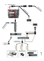
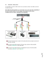
Страница 8: ...Page 8 2 2 Connection schema...

Страница 9: ...f the communication cable to the 8pin connector of the video interface Remove the female 10pin connector of the factory harness at the rear side of the monitor and connect it to the male 10pin connect...

Страница 10: ...logue connection see 6pin assignment above 2 4 Connection picture signal cable Remove the female Mini USB connector from the rearside of the blackbox and connect it to the male black Mini USB connecto...

Страница 11: ...the interface Due to changes in the production of the vehicle manufacturer there s always a possibility of incompatibility Connect the female 6pin connector of the video cable to the male 6pin connec...

Страница 12: ...ld carry 12V while the reverse gear is engaged Note Do not forget to set dip5 of video interface to ON before testing 2 5 1 1 Case 1 CAN box receives the reverse gear signal If the CAN bus box deliver...

Страница 13: ...ditional open relay e g AC RW 1230 with wiring AC RS5 or filter e g AC PNF RVC is required Below schema shows the use of a relay normally open Connect the green cable of the 6pin to 12pin cable to the...

Страница 14: ...ode of the factory infotainment If 2 AV sources shall be connected to the infotainment additional electronic is necessary to switch the audio signals 2 6 Connection Video Interface and external keypad...

Страница 15: ...settings have to be done separately for AV1 AV2 and CAMERA IN while the corresponding input is selected and visible on the monitor Note The OSD menu is only shown when a working video source is conne...

Страница 16: ...ng the vehicle s Call off button Each press will switch to the next enabled input If all inputs are enabled the order is Factory video video IN1 video IN2 factory video Disabled inputs will be skipped...

Страница 17: ...nabled are skipped Note Alternatively or additionally the white wire of the 6pin cable can be used with a 5 12V pulse to switch the video sources alternatively 4 Specifications BATT ACC range 7V 25V S...

Страница 18: ...is exactly connected according to manual Plugging into head unit does not work when the manual says to plug into monitor and vice versa Wrong monitor settings of video interface Try different combina...

Страница 19: ...or ALL is ON function for Asian market in the interface OSD Set interface OSD menu item UI CNTRL to ALLOFF or PDCON Not possible to switch video sources by OEM button CAN bus interface does not suppor...

Отзывы: