QUIETCOOLSYSTEMS.COM
11
Installing the QuietCool system is very easy. Simply follow the steps given below:
Determine from down below in which areas you would like to install your QuietCool fan. Go up into the attic to
mark the exact location for the fan. Make sure you have a minimum of 30” of clearance. Take the cardboard
cutout template and a small screwdriver with you. Make sure the template fits between the framing.
1. Open and unpack your QuietCool fan.
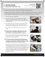
2. When you have chosen your exact spot, place the provided
template on the spot and mark it at each corner by pushing the
screwdriver through at each corner to make a hole so that you can
find it from below.
3. From below, place the cut-out template on the ceiling, making
sure that you have at least 2 inches of clearance all around it.
While holding the template in place, mark its outline with a pencil.
4. Using a drywall saw or similar device, cut out the hole in the
ceiling.
TIP:
If your attic is very tight, you may want to wire your
QuietCool motor housing before bringing it into the attic.
Please follow the wiring diagrams that start on page 13.
5. Take the main assembly, which includes the motor housing, damper
box, and duct into the attic through the crawl hole and move into
position near the ceiling cut-out hole.
TIP:
If your attic access is far from your fan location, you can
remove the duct from the motor housing and pass the motor
housing, duct, and damper box through the ceiling cut out hole
and reattach the duct to the motor housing in the attic.
6. Pre-screw two wood screws into the rafter almost all the way. Using
the keyholes on the straps, hang the motor head from the two wood
screws and tighten the screws. Make sure that the handy box on
the motor head is at the very top. Secure duct to damper box using
the duct clasps. Make sure the housing is angeled slightly up and
the duct has a gentle 90 degree bend to help reduce noise level.
The angle is important so the fan does not disturb any blown-in
insulation in your attic.
WELCOME
INST
ALLA
TION
WIRING
OPERA
TION
W
ARRANTY
NOTE:
Once your QuietCool fan is hung, it’s time to go below and install the damper box and
ceiling grille.
NOTE:
If you are installing the damper box with a vertical adapter, please follow the instructions
on page 12.
7. Look through the hole and make sure there are no kinks or twists in the ducting. Pull the damper box
down through the hole in the ceiling.
NOTE:
The QuietCool Damper Box includes removable flanges in the case that you are installing
the damper box between studs that are exactly 16” on center. To remove the flanges, simply take
a screwdriver and pry between the flange surface and the damper box. Do this along the entire
edge of the flange and it will pop off.
NOTE:
The damper box flange is designed to sit on the backside of the drywall, inside the attic.
Do not attempt to install the damper box with the flanges on the outer side of the drywall in the
home.
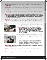
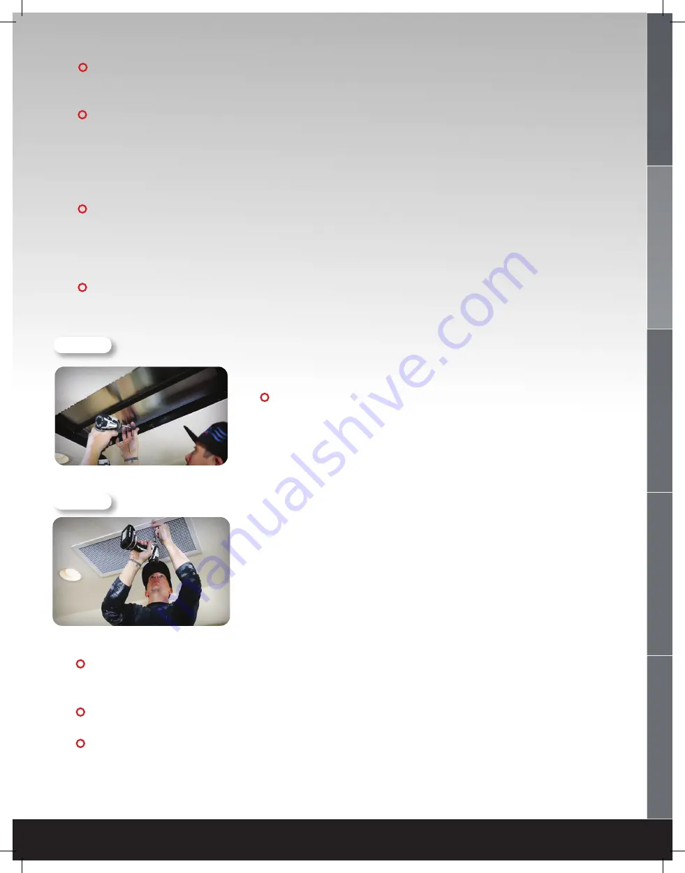
8. Using the included drywall screws, fasten the damper box to both
the drywall and the joist in the attic.
NOTE:
Remember that you must fasten the damper box to
the ceiling joists AND drywall. The purpose of this is to make
sure the damper box stays in place when you are screwing
in the grille. If you do not fasten the damper box to the
drywall, the damper box will not stay in place when attempting
to screw in the grille.
9. Remove ceiling grille and screws from its packaging. Center the
grille over the damper box. Install the grille with the white screws
provided by screwing through the drywall into the flange of the
damper box.
10. Return to the attic. Using the nylon straps and the long wood
screws provided, support the duct to the framing. This will
stabilize the entire assembly. Replace any insulation that was
removed. The installation of the fan is now complete.
NOTE:
Some ceiling surfaces are uneven and may cause a small gap to be present. This can easily
be caulked later if excessive.
NOTE:
Local building codes and standards must be adhered to in the installation of this unit.
NOTE:
Additional insulation can be added to the top of the damper box to provide additional
sound dampening.
Figure 3.1E
Figure 3.1F
!
!
!!
!!
!!
!!
!!
!!
!!


