


• Remove the lower back panel. (Refer to Fig. 2)
• Loosen the battery hold-down strap and install the battery. Tighten
the hold-down strap to make sure the battery is secure.
• Connect the positive cable (identified with red heat-shrink near the
connector) to the positive battery terminal.
• Connect the negative cable to the negative battery terminal.
• Reinstall the back panel. (Fig. 2)
3. RESCUE 4050 only
• Connect the supplied air hose to the threaded air outlet on the
back panel. (Fig. 3)
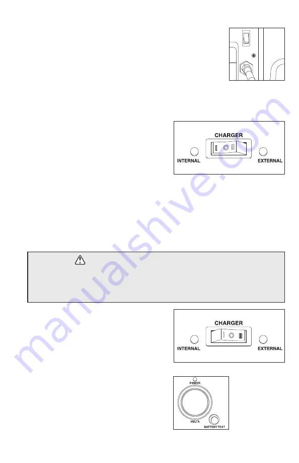
Charging the internal battery
• The battery charger power cord is permanently
installed and wrapped around the cleats on the
back of the unit.
• Plug the unit into a 120V AC outlet.
• Set the rocker switch on the front of the unit to
INTERNAL. (Fig. 4)
o
When the battery is charging, the LED light will be lighted red. When the battery is fully
charged the LED will turn green.
o
The charger will go to float mode when the battery is fully charged (13.6V).
o
Check the charge of the internal battery using the battery test button and voltage gauge
on the front of the unit. (Fig. 6)
o
Connect the positive (red) battery clamp to the
positive terminal of the battery to be charged.
o
Connect the negative (black) battery clamp to the
negative terminal of the battery to be charged.
o
The voltmeter on the front of the RESCUE
4000/4050 will automatically read the voltage of
the external battery.
o
If the voltage is above 5V, plug the power cord
of the RESCUE 4000/4050 into a 120V AC outlet
and set the rocker switch on the front of the unit to
EXTERNAL. (Fig. 5)
o
When the battery is charging, the LED will be
lighted red. When the battery is fully charged, the
LED will turn green.
• Be sure the switch on the back of the RESCUE 4000/4050 is in the OFF position before
connecting clamps to a battery.
• If the voltage reading is below 5V, OR if there is no reading at all on the volt meter,
DISCONNECT THE BATTERY CABLES. DO NOT ATTEMPT TO CHARGE.
WARNING – Risk of explosion or fire
Using your RESCUE 4000/4050
Charging an external battery
3
Fig. 4
Fig. 3
Fig. 5
Fig. 6


