


M20 Hardware Design
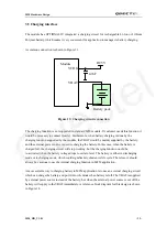
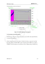
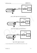
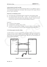
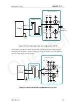
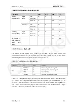
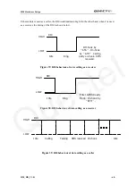
CUSTOMER(DTE)
TXD
RXD
GND
Module(DCE)
Serial port1
TXD1
RXD1
GND
Figure 22: Connection of software debugging
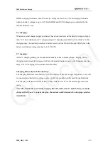
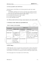
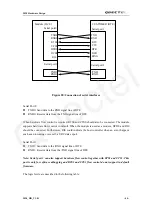
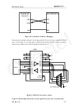
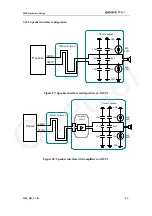
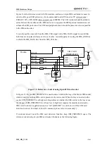
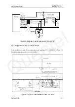
The serial port 0 and the serial port 1 don’t support the RS-232 level, but only support the CMOS
level. A level shifter IC or circuit may be inserted between DCE and DTE. Figure 23 shows a
reference level shifter circuit when the module is connected to a PC.
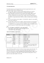
9
8
7
6
5
4
3
2
1
15
14
8
9
11
12
5
7
6
10
4
26
2
27
13
18
20
21
16
17
19
22
23
24
3
1
25
28
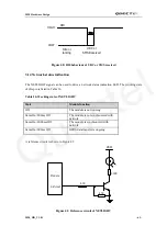
GND
TO PC serial port
SP3238
3V
GND
GND
T5OUT
/SHUTDOWN
V+
GND
V-
VCC
T4OUT
T2OUT
T3OUT
T1OUT
R3IN
R2IN
R1IN
/STATUS
3V
ONLINE
R1OUT
R2OUT
R3OUT
/R1OUT
GND
T5IN
T4IN
T3IN
T2IN
T1IN
C2+
C2-
C1-
C1+
RXD
DTR
RTS
RI
CTS
TXD
DCD
Module
Figure 23: RS-232 level converter circuit
Note
:
For detailed information about serial port application, please refer to document [10]
M20_HD_V1.01
- 47 -
Quectel


