background image


GNSS  Module  Series 

                                                                                                        L80&L80-R&L86&LC86L  EVB  User  Guide 

L80&L80-R&L86&LC86L_EVB_User_Guide                                                                                            25 / 30 


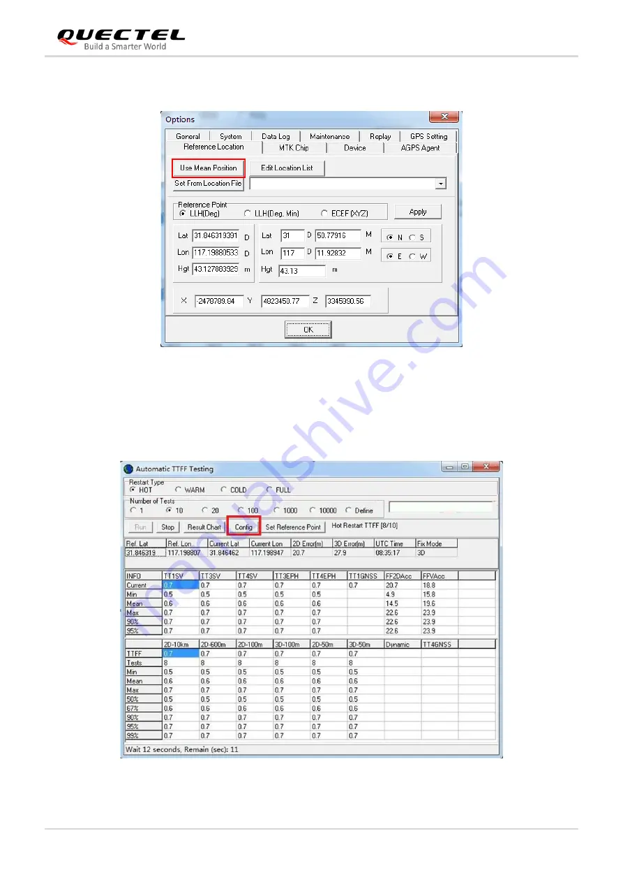
After that, the interface will be shown as below. C

lick “

Use


Mean Position

” and then “

OK

”. 


Figure 17: Click Use Mean Position 


Step 3: 

 Return to the interface shown as below and click 

Config

” to get to TTFF Configuration interface. 


Then, 

set “

TTFF Time- out (sec)

”, and finally click “

OK

”. 


Figure 18: Click Configuration 

Содержание L80

Страница 1: ...L80 L80 R L86 LC86L EVB User Guide GNSS Module Series Version 2 0 Date 2020 12 22 Status Released www quectel com ...

Страница 2: ...thout prior notice Disclaimer While Quectel has made efforts to ensure that the functions and features under development are free from errors it is possible that these functions and features could contain errors inaccuracies and omissions Unless otherwise provided by valid agreement Quectel makes no warranties of any kind implied or express with respect to the use of features and functions under d...

Страница 3: ...mation of Quectel Transmitting reproducing disseminating and editing this document as well as using the content without permission are forbidden Offenders will be held liable for payment of damages All rights are reserved in the event of a patent grant or registration of a utility model or design Copyright Quectel Wireless Solutions Co Ltd 2020 All rights reserved ...

Страница 4: ...Guide 3 30 About the Document Revision History Version Date Author Description 1 0 2014 08 18 Bond SUN Initial 2 0 2020 12 22 Ronnie HU 1 Incorporated the information of L80 L80 R and L86 EVB user guides created separately years ago into this manual 2 Added the applicable module LC86L ...

Страница 5: ...ories 9 2 3 EVB and Accessories Assembly 10 3 EVB Interfaces 12 3 1 Micro USB Interface 12 3 2 Antenna Interface 12 3 3 Switches and Buttons 13 3 4 Status Indication LEDs 14 3 5 Test Points 15 4 EVB Operation Procedures 17 4 1 Communication Through Micro USB Interface 17 4 2 Firmware Upgrade 18 5 Using PowerGPS 20 5 1 COM and Baud Rate Setting 20 5 1 1 Interface Explained 21 5 2 PMTK Command Sendi...

Страница 6: ...30 Table Index Table 1 Available Interfaces 8 Table 2 List of Accessories 10 Table 3 Switches and Buttons 14 Table 4 Status Indication LEDs 15 Table 5 Pin Description of Test Points J401 16 Table 6 PowerGPS Interface Explained 21 Table 7 Related Documents 28 Table 8 Terms and Abbreviations 28 ...

Страница 7: ...LEDs 14 Figure 8 GNSS EVB Test Points J401 15 Figure 9 USB Ports 17 Figure 10 COM Port Setting Interface of QCOM 17 Figure 11 FlashTool Configurations for Firmware Upgrade 18 Figure 12 PowerGPS Interface Not Connected 20 Figure 13 PowerGPS Interface Connected 21 Figure 14 PMTK Command Sending via PowerGPS 23 Figure 15 Static TTFF Testing via PowerGPS 24 Figure 16 Choose Reference Location 24 Figur...

Страница 8: ...o all manuals supplied with the product Otherwise Quectel assumes no liability for customers failure to comply with these precautions Ensure that the use of the product conforms to the national safety and environmental regulations and is allowed to be used in the country and in the required environment Keep away from explosive and flammable materials The use of electronic products in extreme power...

Страница 9: ...ide 8 30 2 General Overview 2 1 Top View The following figure illustrates the top view of the EVB Figure 1 Top View of the EVB Table 1 Available Interfaces SN Reference Number Description A J403 Antenna connector 1 B D303 D304 D305 D306 D307 Indication LEDs 2 see Chapter 3 4 for details ...

Страница 10: ...7 AADET_N is invalid for this module as well Additionally D305 and D306 are not supported by any of the applicable modules 3 3 The L80 and L80 R modules do not support the FORCE_ON interface so the FORCE_ON button is invalid for those modules 2 2 EVB Kit Accessories Figure 2 EVB Kit Accessories C J401 Test points D U404 The module E S201 USB SD Card USB SD Card alternation switch F S101 POWER swit...

Страница 11: ...and its accessories see the instruction sheet provided in the EVB Kit On the following figure you can see the EVB and the accessories when they are assembled Items Description Quantity EVB Evaluation board 1 USB Cable Micro USB cable 1 Antenna Active GNSS antenna 1 1 USB Flash Drive USB flash drive including the module related documents tools and drivers 1 Instruction Sheet A sheet of paper giving...

Страница 12: ... R L86 LC86L EVB User Guide L80 L80 R L86 LC86L_EVB_User_Guide 11 30 Figure 3 EVB and Accessories Assembly As the L80 R module does not support an external antenna the active antenna is not included in the EVB kit for L80 R NOTE ...

Страница 13: ... EVB Interfaces 3 1 Micro USB Interface The micro USB connector is used for both power supply input and NMEA sentences output Figure 4 Micro USB Connector 3 2 Antenna Interface The EVB is mounted with an antenna connector for the connection with an external active GNSS antenna Micro USB Connector ...

Страница 14: ...de 13 30 Figure 5 Antenna Connector The antenna connector is invalid for the L80 R module as the module does not support an external antenna 3 3 Switches and Buttons The following figure illustrates the switches and buttons on the EVB Figure 6 Switches and Buttons Antenna Connector NOTE ...

Страница 15: ...ure 7 Status Indication LEDs Reference No Name I O Description S101 POWER PI Powers the EVB on off S201 USB SD USB SD alternation switch DI Switches the data communication port Keep the switch on USB side as the modules do not support the SD card function S302 FORCE_ON 1 DI Short press press and then release the button to wake up the module from the backup mode S301 RESET DI Short press press and ...

Страница 16: ...d by any of the applicable modules 3 5 Test Points The following figure illustrates the EVB test points Figure 8 GNSS EVB Test Points J401 Reference No Name I O Description D303 1PPS DO Flash successful position fix The frequency is 1 Hz Extinct no position fix D304 TXD DO Flash Data output from TXD pin Extinct No data output from TXD pin D307 AADET_N 1 DO Bright EVB uses the external active anten...

Страница 17: ...EVB_User_Guide 16 30 Table 5 Pin Description of Test Points J401 The other pins are not supported by the applicable modules Pin No Signal I O Description 1 GND Ground 2 RESET DI Resets the module 3 1PPS DO 1 pulse per second 4 TXD DO Transmits data 5 RXD DI Receives data NOTE ...

Страница 18: ... Run the USB flash drive on the PC to install the USB driver After installation the USB port numbers can be viewed through a device manager as shown below Figure 9 USB Ports Step 3 Install and then use the QCOM tool provided by Quectel to realize the communication between the module and the PC The following figure shows the COM Port Setting interface of QCOM select the correct COM Port USB port nu...

Страница 19: ...SB interface and then turn on the POWER switch S101 to power on the EVB Step 3 Follow the steps below to start firmware upgrade a Click the Settings Baud rate dropdown list and select the 115200 b Click the Settings COM Port dropdown list and select the COM port c Select the files to be downloaded tick the boxes next to the Reserve and the ROM to select the corresponding file path Reserve correspo...

Страница 20: ...Module Series L80 L80 R L86 LC86L EVB User Guide L80 L80 R L86 LC86L_EVB_User_Guide 19 30 As the L80 R module is the ROM based version without built in Flash the module has no firmware upgrade function NOTE ...

Страница 21: ...1 After EVB accessories are assembled turn on the EVB and start PowerGPS PowerGPS Trial 2 3 5 is used as an illustration in this document After the tool is started the following interface is displayed with 6 default windows Figure 12 PowerGPS Interface Not Connected Step 2 At the bottom of the interface select a correct COM port and baud rate the modules support 9600 bps by default then click the ...

Страница 22: ...n such as CNR message time position speed and precision To find out more about these parameters see the table below Table 6 PowerGPS Interface Explained Icon Explanation A satellite vehicle SV with PRN 65 If the position of SV is near to the centre of the Sky View the elevation angle of SV is close to 90 Dark Blue means that this satellite is being tracked Light blue means that this satellite is n...

Страница 23: ...ellite B for a BeiDou satellite while S means that it is a SBAS satellite Light blue column indicates that the navigation data of this satellite is in use The CNR of PRN 3 is 42 dB Hz White column indicates that the navigation data of this satellite is not in use UTC time Latitude degree Longitude degree Position fix The number of satellites being used Horizontal dilution of precision Altitude bas...

Страница 24: ... testing conditions The TTFF can be tested under full cold start cold start warm start or hot start conditions and the number of tests can be selected from 1 10 20 100 1000 and 10000 Click the Run button to start the test The test can be stopped by clicking the Stop button The following are the detailed configuration steps during TTFF testing Step 1 Start MTK menu and then click Static TTFF Testin...

Страница 25: ...0 R L86 LC86L_EVB_User_Guide 24 30 启动类型 测试次数 Restart Type The Number of Tests Figure 15 Static TTFF Testing via PowerGPS Step 2 Click Set Reference Point and the Options window is shown as below Next choose Reference Location Figure 16 Choose Reference Location ...

Страница 26: ...After that the interface will be shown as below Click Use Mean Position and then OK Figure 17 Click Use Mean Position Step 3 Return to the interface shown as below and click Config to get to TTFF Configuration interface Then set TTFF Time out sec and finally click OK Figure 18 Click Configuration ...

Страница 27: ...lected it is recommended to set TTFF Time out sec to 10 s If warm start is selected it can be set as 50 s Lastly if cold start is selected it can be set as 100 s TTFF Time out sec can help judge TTFF and save time Step 4 After all above operations have been performed click the Run button to start the test The test can be stopped by clicking the Stop button ...

Страница 28: ...VB User Guide L80 L80 R L86 LC86L_EVB_User_Guide 27 30 Figure 20 Click Run Stop Button Step 5 After testing you can see the testing results displayed visually in charts The test results are stored in the directory where the tool is installed ...

Страница 29: ...el_L80_GNSS_Protocol_Specification L80 GNSS Protocol Specification 6 Quectel_L80 R_GNSS_Protocol_Specification L80 R GNSS Protocol Specification 7 Quectel_L86_GNSS_Protocol_Specification L86 GNSS Protocol Specification 8 Quectel_L76 LB L26 LB LC86L_GNSS_ Protocol_Specification L76 LB L26 LB LC86L GNSS Protocol Specification 9 Quectel_L80 L86 LC86L_Reference Design L80 L86 LC86L Reference Design 10...

Страница 30: ...d LED Light Emitting Diode Micro USB Micro Universal Serial Bus NMEA National Marine Electronics Association PC Personal Computer PMTK MTK Proprietary Protocol PPS Pulse Per Second PRN Pseudorandom Noise ROM Read Only Memory RXD Receive Data Pin SBAS Satellite Based Augmentation System SD Card Secure Digital Card SPS Standard Positioning Service SV Satellite Vehicle TTFF Time to First Fix TXD Tran...

Страница 31: ...GNSS Module Series L80 L80 R L86 LC86L EVB User Guide L80 L80 R L86 LC86L_EVB_User_Guide 30 30 UTC Universal Time Coordinated WGS84 World Geodetic System 1984 ...

Отзывы: