Quectel HCM111Z TE-B Скачать руководство пользователя страница 10


Bluetooth  Module  Series


HCM111Z_TE-B_User_Guide                                                                                                                      9  / 22


2


Product  Overview 


HCM111Z TE-B is a Bluetooth development board with Arduino interface, it can be used separately for 

developing and debugging applications. 


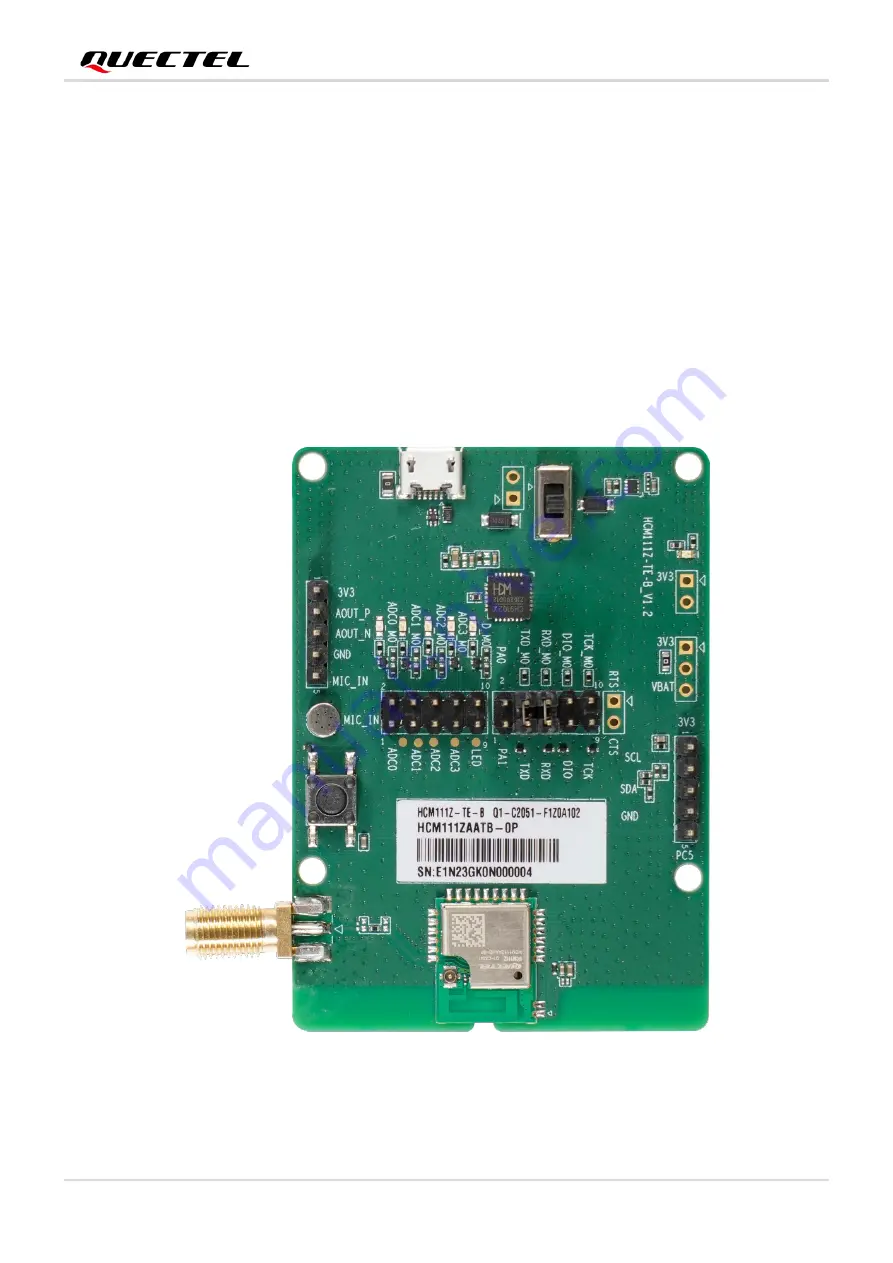
2.1.  Top and Bottom Views 


Figure 1: Top View


Содержание HCM111Z TE-B

Страница 1: ...HCM111Z_TE B_User_Guide 1 22 HCM111Z TE B User Guide Bluetooth Module Series Version 1 0 0 Date 2023 09 16 Status Preliminary...

Страница 2: ...employ commercially reasonable efforts to provide the best possible experience you hereby acknowledge and agree that this document and related services hereunder are provided to you on an as availabl...

Страница 3: ...o implement module functionality certain device data are uploaded to Quectel s or third party s servers including carriers chipset suppliers or customer designated servers Quectel strictly abiding by...

Страница 4: ...use interference on sensitive medical equipment so please be aware of the restrictions on the use of wireless devices when in hospitals clinics or other healthcare facilities Terminals or mobiles oper...

Страница 5: ...ooth Module Series HCM111Z_TE B_User_Guide 4 22 About the Document Revision History Version Date Author Description 2023 09 16 Janson CHEN Creation of the document 1 0 0 2023 09 16 Janson CHEN Prelimi...

Страница 6: ...nent Placement 11 2 3 Arduino Interface Definition Diagram 13 2 4 Key Features 14 2 5 Functional Diagram 15 3 Application Interfaces 16 3 1 Operation Procedure with Single Board 16 3 1 1 Interface Dia...

Страница 7: ...Bluetooth Module Series HCM111Z_TE B_User_Guide 6 22 Table Index Table 1 Component Information 11 Table 2 Key Features of TE B 14 Table 3 Related Documents 22 Table 4 Terms and Abbreviations 22...

Страница 8: ...ace Definition 13 Figure 5 Functional Diagram of TE B 15 Figure 6 Interface Diagram of Using TE B Alone 16 Figure 7 USB to UART Interface Displayed on PC 17 Figure 8 Schematic diagram of AT command an...

Страница 9: ...ications with Quectel HCM111Z TE B conveniently Quectel supplies corresponding development board HCM111Z TE B to test the module This document can help customers quickly understand HCM111Z TE B interf...

Страница 10: ...M111Z_TE B_User_Guide 9 22 2 Product Overview HCM111Z TE B is a Bluetooth development board with Arduino interface it can be used separately for developing and debugging applications 2 1 Top and Botto...

Страница 11: ...Bluetooth Module Series HCM111Z_TE B_User_Guide 10 22 Figure 2 Bottom View...

Страница 12: ...2 D0201 U0101 U0301 U0201 R0202 Figure 3 Component Placement Table 1 Component Information Component RefDes Description Comment Power Supply Interfaces J0301 USB power supply interface Typical supply...

Страница 13: ...bridge U0301 RF antenna interface J0205 RF SMA connector Test Point J0207 Tests the basic functions of the module ICs U0101 LDO Convert the voltage from 5 V to 3 3 V U0301 USB to UART Bridge Bluetoot...

Страница 14: ...2 2 3 Arduino Interface Definition Diagram ANT_BT RESET_P MIC_IN UART0_TXD UART0_RXD 3 3 V 3 3 V 3 3 V GND GND GND 3 3 V 5 V GND GPIO6 GPIO4 GPIO3 GPIO1 GPIO2 GPIO5 GPIO7 LEDGPIO9 GPIO11 GPIO8 GPIO10...

Страница 15: ...ply voltage range 1 8 4 3 V Typical supply voltage 3 3 V Transmitting Power 7 5 dBm 2 dB Temperature Range Operating temperature range 40 to 85 C 1 Storage temperature range 45 to 95 C USB to UART Int...

Страница 16: ...1Z_TE B_User_Guide 15 22 2 5 Functional Diagram HCM111Z U0201 Micro USB J0301 USB to UART Bridge U0301 ANT_BT J0205 Switch S0101 LDO U0101 Arduino J0201 RESET_N SW0201 J0203 J0202 Arduino J0204 Figure...

Страница 17: ...alone to upgrade firmware and to debug applications based on HCM111Z TE B The following describes the operation procedures of TE B in different operation modes 3 1 Operation Procedure with Single Boar...

Страница 18: ...connected with a jumper cap or not 3 Switch S0101 power switch to ON 4 Connect the J0301 USB power supply interface with PC via Micro USB cable Serial port information will be shown on Device Manager...

Страница 19: ...Bluetooth Module Series HCM111Z_TE B_User_Guide 18 22 Figure 8 Schematic diagram of AT command and Data Transmission Figure 9 Schematic diagram of Firmware Upgrade...

Страница 20: ...B DC power analyzer Wire soldering iron tin wire and wire stripping pliers etc to weld the power supply cord on TE B This power consumption test guide is based on Keysight s N6705C DC power analyzer...

Страница 21: ...consumption of the module on the modified TE B 1 Insert the USB cable 2 Set the output voltage on N6705C to 3 3 V and connect the positive and negative wires of N6705C to the two wires VBAT GND welde...

Страница 22: ...Bluetooth Module Series HCM111Z_TE B_User_Guide 21 22 Figure 11 TE B Wiring Diagram...

Страница 23: ...Z_AT Command 2 Quectel_HCM111Z_Hardware Design Abbreviation Description DC Direct Current GND Ground IC Integrated Circuit LDO Low dropout Regulator MIC Microphone PC Personal Computer RF Radio Freque...

Отзывы: