LTE Standard Module Series
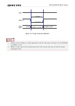
The power-up scenario is illustrated in the following figure.
V
IL
≤
0.5 V
VBAT
PWRKEY
≥
500 ms
RESET_N
STATUS
(OD)
I nactive
Active
UART
NOTE 1
Inactive
Active
USB
≥
10 s
VDD_EXT
USB_BOOT
≥
100 ms. After this time, the pin can be set
high level by an external circuit.
About 22 ms
About 5 ms
≥
10 s
≥
10 s
Figure 11:
Power-up Timing
.
3.6. Turn Off
The following procedures can be used to turn off the module:
1. Make sure that VBAT is stable before pulling down PWRKEY pin. It is recommended that the time
difference between powering up VBAT and pulling down PWRKEY pin is no less than 30 ms.
2.
PWRKEY can be pulled down directly to GND with a recommended 4.7 kΩ resistor if module needs
to be powered on automatically and shutdown is not needed.
NOTE


