Queclink GV50 Скачать руководство пользователя страница 7

GV50 (P) User Manual 


TRACGV50UM001   


-  6  - 

1.


Introduction 

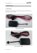
GV50(P)  is  a  mini  GPS  tracker  designed  for  a  wide  variety  of  vehicle  tracking  applications.  Its 
built-in  GPS  receiver  has  superior  sensitivity  and  fast  time  to  first  fix.  Its  quad  band  GPRS 
subsystem supports 850/1900 MHz, allowing the GV50(P)'s location to be monitored in real time 
or periodically tracked by a backend server and mobile devices. Its built-in 3-axis accelerometer 
allows  motion  detection  and  extends  battery  life  through  sophisticated  power  management 
algorithms. System integration is straightforward as complete documentation is provided for the 
full featured @Track protocol. The @Track protocol supports a wide variety of reports including 
emergency, geo-fence boundary crossings, low battery and scheduled GPS position.


1.1 Reference 

Table 1. GV50(P) Protocol Reference 

SN 

Document name 

Remark 

[1] 

GV50 @Track Air Interface Protocol 

The  air  protocol  interface  between  GV50(P)  and 
backend server. 


Содержание GV50

Страница 1: ...GV50 P User Manual GPRS GNSS Tracker TRACGV50UM001 Version 1 01...

Страница 2: ...ustomer s possession Furthermore system validation of this product designed by Queclink within a larger electronic system remains the responsibility of the customer or the customer s system integrator...

Страница 3: ...ace Definition 8 2 3 1 GV50 External Interface 8 2 3 2 GV50P External Interface 9 2 3 3 Internal Interface 9 2 4 GV50 P Extension Cable Color 10 3 Getting Started 12 3 1 Opening the Case 12 3 2 Closin...

Страница 4: ...ABLE 2 GV50 PARTS LIST 8 TABLE3 GV50 P PARTS LIST 8 TABLE 4 DESCRIPTION OF 2 PIN CABLE 9 TABLE 5 DESCRIPTION OF 4 PIN CABLE 9 TABLE 6 GV50 2 PIN EXTENSION CABLE COLOR DEFINITION 10 TABLE 7 GV50P 4 PIN...

Страница 5: ...BLE 9 FIGURE 4 GV50P 4 PIN CABLE 9 FIGURE 5 GV50 P MICRO USB CONNECTOR 10 FIGURE 6 OPENING THE CASE 12 FIGURE 7 CLOSING THE CASE 12 FIGURE 8 INSTALLING A SIM CARD 13 FIGURE 9 INSTALLING THE INTERNAL B...

Страница 6: ...GV50 P User Manual TRACGV50UM001 5 0 Revision History Revision Date Author Description of Change 1 00 2016 11 28 Pablo Dang Initial 1 01 2017 06 17 Pablo Dang Added GV50P related information...

Страница 7: ...nd mobile devices Its built in 3 axis accelerometer allows motion detection and extends battery life through sophisticated power management algorithms System integration is straightforward as complete...

Страница 8: ...7 2 Product Overview 2 1 Check Parts List Before starting check all the following items have been included with your GV50 P If anything is missing please contact your supplier Figure 1 Appearance of G...

Страница 9: ...le 2 GV50 Parts List Name Picture GV50 Locator User Cable Table3 GV50 P Parts List Name Picture GV50 P Locator User Cable 2 3 Interface Definition 2 3 1 GV50 External Interface GV50 has a 2 PIN cable...

Страница 10: ...rnal Interface The GV50P has a 4 PIN cable The pin definition of the 4 pin power cable is shown below Figure 4 GV50P 4 Pin Cable Table 5 Description of 4 Pin Cable Index Description Remark 1 VIN red E...

Страница 11: ...nnector 2 4 GV50 P Extension Cable Color Table 6 GV50 2 Pin Extension Cable Color Definition Pin No Definition Color Cable 1 VIN red 2 GND black Table 7 GV50P 4 Pin Extension Cable Color Definition Pi...

Страница 12: ...GV50 P User Manual TRACGV50UM001 11 4 IGN white...

Страница 13: ...ase Figure 6 Opening the Case Insert the triangular pry opener into the gap of the case as shown below and push the opener up until the case unsnaps 3 2 Closing the Case Figure 7 Closing the Case Plac...

Страница 14: ...attery to OFF position Slide the holder right to open the SIM card Insert the SIM card into the holder as shown below with the gold colored contact area facing down Take care to align the cut mark Clo...

Страница 15: ...be in the OFF position when shipped on an aircraft 2 When the switch is in the OFF position the battery cannot be charged or discharged 3 To reset the device Remove the external DC power and then swi...

Страница 16: ...t are CELL LED and GPS LED LED Device Status LED Status CELL Note 1 Device is searching GSM network Fast flashing Device has been registered to GSM network Slow flashing SIM card needs pin code to unl...

Страница 17: ...n the user is encouraged to try to correct the interference by one or more of the following measures Reorient or relocate the receiving antenna Increase the separation between the equipment and receiv...

Отзывы: