background image


GV300VC User Manual


2. Product Overview  

2.1


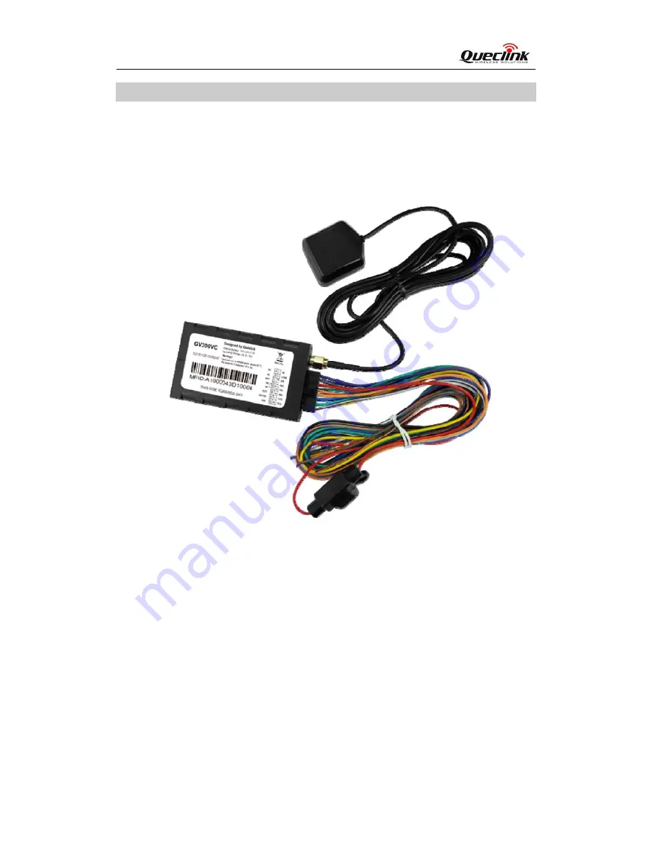
Check Parts List  

Before  starting,  check  whether  all  the  following  items  have  been  included  with  your  GV300.  If 

anything is missing, please contact your supplier.  


Figure 1.


Appearance of GV300VC 


TRACGV300VCUM001


- 8 - 


Содержание gv300vc

Страница 1: ......

Страница 2: ...ession Furthermore system validation of this product designed by Queclink within a larger electronic system remains the responsibility of the customer or the customer s system integrator All specifica...

Страница 3: ...4 GV300VC User Cable Colour 11 3 Get Started 12 3 1 Open the Case 12 3 2 Close the Case 12 3 3 Install the Internal Backup Battery 13 3 4 Switch on the Backup Battery 13 3 5 Install the External GPS...

Страница 4: ...4 DESCRIPTION OF 16 PIN CONNECTIONS 10 TABLE 5 GV300VC USER CABLE COLOUR DEFINITION 11 TABLE 6 GPS ANTENNA SPECIFICATION 14 TABLE 7 ELECTRICAL CHARACTERISTICS OF IGNITION DETECTION 16 TABLE 8 ELECTRIC...

Страница 5: ...ND ON OFF POSITION 13 FIGURE 7 GPS ANTENNA OF GV300VC 14 FIGURE 8 TYPICAL POWER CONNECTION 15 FIGURE 9 TYPICAL IGNITION DETECTION 16 FIGURE 10 TYPICAL DIGITAL INPUT CONNECTION 17 FIGURE 11 TYPICAL ANA...

Страница 6: ...GV300VC User Manual TRACGV300VCUM001 6 0 Revision History Revision Date Author Description of change 1 00 2014 09 01 York Zhu Initial...

Страница 7: ...ded battery life through sophisticated power management algorithms System integration is straightforward as complete documentation is provided for the full featured Track protocol The Track protocol s...

Страница 8: ...duct Overview 2 1 Check Parts List Before starting check whether all the following items have been included with your GV300 If anything is missing please contact your supplier Figure 1 Appearance of G...

Страница 9: ...GV300VC User Manual TRACGV300VCUM001 9 2 2 Parts List Table 3 Parts List Name Picture GV300VC Locator 80 49 26 mm User Cable GPS Antenna Optional DATA_CABLE_M Optional...

Страница 10: ...Index Description Comment 1 NC Leave it floating 2 AGND Analog ground 3 IGN Ignition input positive trigger 4 RXD UART RXD RS232 5 TXD UART TXD RS232 6 GND Power and digital ground 7 OUT3 Open drain 1...

Страница 11: ...Colour definition Definition Color PIN No Cable PIN No Color Definition OUT2 Yellow 8 16 Brown White AD2 OUT3 Brown 7 15 Green AD1 IN3 GND Black 6 14 Blue OUT1 TXD White Black 5 13 Orange IN1 RXD Gree...

Страница 12: ...angular pry opener into the gap of the case as shown above and push the opener up until the case is unsnapped 3 2 Close the Case Figure 4 Close the Case Place the cover on the bottom in the position a...

Страница 13: ...3 4 Switch on the Backup Battery To use the GV300VC backup battery the switch must be in the ON position The switch on the case and the ON OFF position are shown below Figure 6 Switch and ON OFF posi...

Страница 14: ...Table 6 GPS Antenna Specification GPS antenna Specification Frequency 1575 42MHz Bandwidth 5 MHz Beam width 120 deg Supply voltage 2 7V 3 3V Polarization RHCP Gain Passive 0 dBi min Active 15dB Impeda...

Страница 15: ...GV300VC User Manual Figure 8 Typical Power Connection 3 7 Ignition Detection Table 7 Electrical Characteristics of Ignition Detection Logical status Electrical characteristics Active 5 0V to 32V Inact...

Страница 16: ...example the power source for the FM radio IGN signal can be configured to start transmitting information to the backend server when ignition is on and enter the power saving mode when ignition is off...

Страница 17: ...is a multifunction pin it can be configured as a digital input or an analog input 3 10 Digital Outputs There are three digital outputs on GV300VC All are of open drain type and the maximum drain curr...

Страница 18: ...will latch the output state during reset 2 Many modern relays come with a flyback diode pre installed internal to the relay itself If the relay has this diode ensure the relay polarity is properly con...

Страница 19: ...e has registered to CDMA2000 network Slow flashing Note 4 GPS note 2 GPS chip is powered off OFF GPS sends no data or data format error occurs Slow flashing GPS chip is searching GPS info Fast flashin...

Страница 20: ...figured to turn off after a period of time using the configuration tool 3 Fast flashing for CELL LED is about 60 ms ON 780 ms OFF for GPS LED and PWR LED is about 100 ms ON 100 ms OFF 4 Slow flashing...

Страница 21: ...ainst harmful interference in a residential installation This equipment generates use s and can radiate radio frequency energy and if not installed and used in accordance with the instructions may cau...

Отзывы: