


™
EN:
The Luxy Smart Switch is the world's first switch that is a light itself. It gently illuminates in 16 million colours
and can be used standalone as a switch to turn on/off the light connected to it and as an ambient light for a gentle
illumination of your home. You can also use it as a smart home device and enjoy plenty of other functionalities it
offers.
PACKAGE CONTENTS
Luxy Smart Switch, glass frame, mounting frame with claws, installation manual and S2 DSK label
INSTALLATION
1. To prevent electrical shock and/or equipment damage, disconnect electrical power at the main fuse or circuit
breaker before installation and maintenance.
2. Be aware that even if the circuit breaker is off, some voltage may remain in the wires — before proceeding with
the installation, be sure no voltage is present in the wiring.
3. Take extra precautions to avoid accidentally turning on the device during installation.
4. Connect the device exactly according to the diagram.
5. Place the antenna as far as possible from metal elements as they may cause signal interference.
6. Do not shorten the antenna.
Epilepsy warning!
This product can trigger epileptic seizures, especially with photosensitive people.
Danger of electrocution!
Installation of this device requires a great degree of skill and may be performed only by a licensed and qualified
electrician. Please keep in mind that even when the device is turned off, voltage may still be present in the device’s
terminals.
Note!
Do not connect the device to loads exceeding the recommended values. Connect the device exactly as shown in the
provided diagrams. Improper wiring may be dangerous and result in equipment damage.
Electrical installation must be protected by directly associated overcurrent protection fuse 10 A, gG or Time lag T,
rated breaking capacity 1500 A (ESKA 522.727) must be used according to wiring diagram to achieve appropriate
overload protection of the device.
The fuse must be installed in fuse holder type: Adele contact 503Si/1 DS
according to the standard IEC60669-2-1.
Z-WAVE™ INCLUSION
SMARTSTART INCLUSION
1. Scan QR code on device label and add S2 DSK to Provisioning List in gateway (hub).
2. Connect the device to the power supply.
3. Make sure the device is within direct range of your Z-Wave gateway (hub.
4. Inclusion will be initiated automatically within few seconds of connection to the power supply and the device
will automatically enrol in your network (when the device is excluded and connected to the power supply it
automatically enters the LEARN MODE state).
MANUAL INCLUSION
1. Enable add/remove mode on your Z-Wave gateway (hub).
2. Connect the device to the power supply.
3. Make sure the device is within direct range of your Z-Wave gateway (hub).
4. Press once on button 3 – right. One press on button 4 – down for enabling full white.
When full white is enabled, press, and hold button 3 – right, between 4 and 6 seconds.
After 6 seconds, the device starts flashing green (1 second ON, 0.5 second OFF). Once
the device receives node ID (after 10 seconds), it stops flashing and turns full green.
The procedure is always available.
Note: In case of S2 Security inclusion a dialog will appear prompting you to enter the corresponding PIN number
(5 underlined digits) that are written on the module label and the label inserted in the packaging (check the
example picture).
IMPORTANT: The PIN code must not be lost.
Z-WAVE EXCLUSION/RESET
Z-WAVE EXCLUSION
1. Connect the device to the power supply.
2. Make sure the device is within direct range of your Z-Wave gateway (hub) or use a hand-held Z-Wave remote to
perform exclusion.
3. Enable exclusion mode on your Z-Wave gateway (hub).
4. Press once on button 3 – right. One press on button 4 – down for enabling full white. When full white is enabled,
press, and hold button 3 – right for 5 seconds. After 5 seconds, the device starts flashing red 1 second ON, 0.5
second OFF.
Once the device loses node ID (after 10 seconds), it stops flashing and turns full red. The procedure is always
available.
NOTE: LEARN MODE state allows the device to receive network information from the controller.
FACTORY RESET
1. Connect the
device
to the power supply
2.
Press once on button 3 – right. One press on button 4 – down for enabling full white.
When full white is enabled,
press and hold button 5
–
left for 10 seconds. After 10 seconds, the device starts flashing blue 1 second on, 0.5
second off.
After 10 seconds the device stops flashing and turns full blue. The procedure is available always. By resetting the
device
, all custom parameters previously set on the
device
will return to their default values, and a node ID will be
deleted. Use this reset procedure only when the gateway (hub) is missing or otherwise inoperable.
NOTE:
See extended manual for custom settings and parameters available for this
device
.
IMPORTANT DISCLAIMER
Z-Wave wireless communication is not always 100 % reliable. This device should not be used in situations in which
life and/or valuables are solely dependent on its functioning. If the device is not recognized by your gateway (hub)
or shows up incorrectly, you may need to change the device type manually and make sure your gateway (hub)
supports
Z-Wave
Plus™
devices.
Contact
us
for
help
before
returning
the
product:
http://qubino.com/support/#email
WARNING
Do not dispose of electrical appliances as unsorted municipal waste, use separate collection facilities. Contact your
local government for information regarding the collection systems available. If electrical appliances are disposed of
in landfills or dumps, hazardous substances can leak into the groundwater and get into the food chain, damaging
your health and well-being. When replacing old appliances with new ones, the retailer is legally obligated to take
back your old appliance for disposal free of charge.
This user manual is subject to change and improvement
without prior notice.
EN
FUNCTIONALITIES
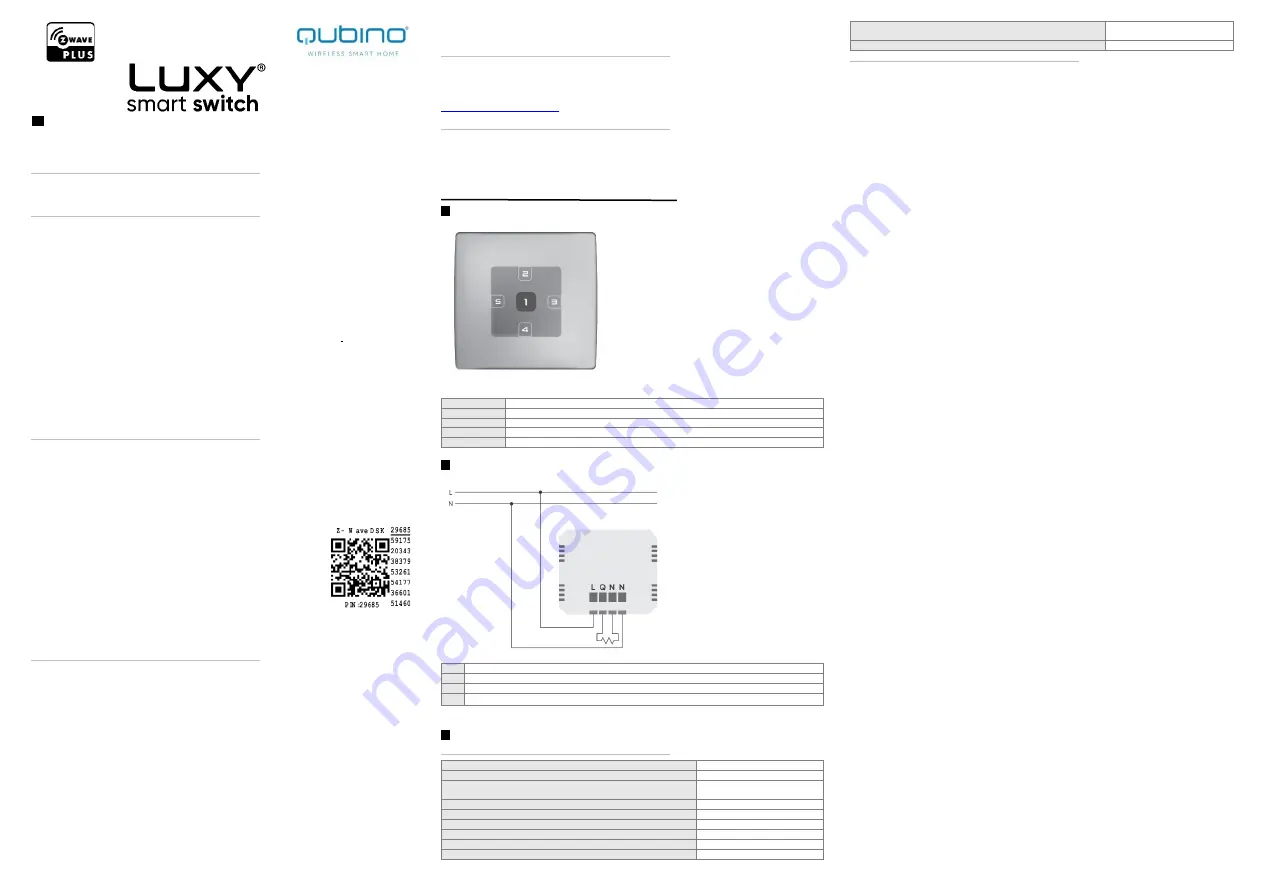
Touch-button specification:
Nr. 1 (CENTER)
Turns ON/OFF the room light or other load connected to it
No. 2 (Up)
Turns ON/OFF the Luxy light
No. 3 (Right)
Switches between 4 different lighting effects (ocean, sunrise, rainbow, and nature)
No. 4 (Down)
Turns ON/OFF the white light on the Luxy
No. 5 (Left)
Starts the colour spectrum and stops at the colour you wish to have
EN
ELECTRICAL DIAGRAM (110 – 240 Vac)
Legend for diagram:
L
Live (line) wire input
Q
Output terminal
N
Neutral output
N
Neutral input/ Entrée du neuter
We recommend using Wago
221-413 splicing connectors when operating with 240 Vac.
EN
TECHNICAL SPECIFICATIONS
Power supply
100 - 240 Vac ±10 %/50/60 Hz
Rated load current of output (resistive load) *
1 x 10 A
Operation temperature
-10 ~ +40 °C
Z-Wave operation range
up to 40 m indoors
Colours
16 - million
Luminance
1090 cd/m
2
Standby/max. consumption
0,5 W / 1,5 W
Installation in boxes
Ø ≥ 60 mm / 2M or 3M
Z-Wave Repeater
Yes/Oui/Ja/Ja
Dimensions (WxHxD) (with packaging
93x90x45 mm / (149x136x53 mm)
Weight (including glass frame)(with packaging)
114 g / (230 g)
CONFIGURATION PARAMETRS
Parameter no. 1 – Relay contact type
Defines the contact type when open/closed contact.
Values (size is 1-byte dec):
• Default value 0
• 0 - NO (normally open) output type
• 1 - NC (normally close) output type
Parameter no 3. – turning off alarming
Values (size is 1-byte dec):
• Default value 1
• 0 – only by Z-Wave command (basic set, switch multilevel set, switch multilevel start/stop
level change, switch color set, switch color start/stop level change, notification report
idle)
• 1 – capacitive input (up, down, left, right) or Z-Wave command (basic set, switch
multilevel set, switch multilevel start/stop level change, , switch color set, switch color
start/stop level change, notification report idle)
Parameter no. 10. – auto on timer
Defines the time after which the device is turned to last known state.
Values (size is 1-byte dec):
• Default value 0
• 0 – disabled
• 30 – 32535 = 30 – 32535 seconds after which the device turns on
Parameter no. 11. – auto off timer
Values (size is 2-byte dec):
Defines the time after which the device is turned to last known state.
• Default value 0
• 0 – disabled
• 30 – 32535 = 30 – 32535 seconds after which the device turns off
Parameter no. 12. – auto on timer relay
Defines the time after which the device's relay is turned to last known state.
Values (size is 2-byte dec):
• Default value 0
• 0 – disabled
• 30 – 32535 = 30 – 32535 seconds after which the device turns on
Parameter no. 13. – auto off timer relay
Defines the time after which the device's relay is turned to last known state.
Values (size is 2-byte dec):
• Default value 0
• 0 – disabled
• 30 – 32535 = 30 – 32535 seconds after which the device turns off
Parameter no. 30. – restore state on power failure
Values (size is 1-byte dec):
• Default value 1
• 1 – enabled (the device will restore state on power failure)
• 0 – disabled (the device will not restore state on power failure and will remain off)
Parameter no. 31. – restore relay state on power failure
Values (size is 1-byte dec):
• Default value 1
• 1 – enabled (the device will restore state on power failure)
• 0 – disabled (the device will not restore state on power failure and will remain off)
Parameter no. 40 – Watt Power Consumption Reporting Threshold for Load
Choose by how much power consumption needs to increase or decrease to be reported. Values
correspond to percentages so if 10 is set (by default), the device will report any power
consumption changes of 10 % or more compared to the last reading.
Values (size is 2-byte dec):
• Default value 10
• 0 - Power consumption reporting disabled
• 1 - 100 = 1 % - 100 % Power consumption reporting enabled. New value is reported only
when Wattage in real time changes by more than the percentage value set in this
parameter compared to the previous Wattage reading, starting at 1 % (the lowest value
possible).
NOTE: Power consumption needs to increase or decrease by at least 1 Watt to be reported,
REGARDLESS of percentage set in this parameter.
Parameter no. 42 – Watt Power Consumption Reporting Time Threshold for Load
Set value refers to the time interval with which power consumption in Watts is reported (0 –
32535 seconds). If 300 is entered (by default), energy consumption reports will be sent to the
gateway (hub) every 300 seconds (or 5 minutes).
Values (size is 2-byte dec):
• Default value 0
• 0 - Power consumption reporting disabled
• 30 - 32535 = 30 - 32535 seconds. Power consumption reporting enabled. Report is sent
according to time interval (value) set here.
Parameter no. 60 – Lock touch for relay only
This parameter enables ONLY the touch functionality for closing/opening the relay meant for
switching ON/OFF the connected light or any other connected load. See chapter 5.4 for
additional information.
Values (size is 1-byte dec):
• Default value 0
• 0 – disabled
• 1 – enabled (the user can switch ON/OFF the connected light or any other connected
load by touching ANY button. Other functionalities (lighting mode, scenes, dimming and


