26-10-2020
manual.zwave.eu/backend/make.php?lang=en&sku=GOAEZMNHWD1
manual.zwave.eu/backend/make.php?lang=en&sku=GOAEZMNHWD1
2/7
- Pull the antenna out of the holder
- Locate the antenna far from metal elements (as far as possible).
- Do not shorten the antenna.
Warning!
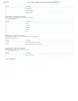
1. The RGBW Controller is suggested to operate in low voltage circuits of 12VDC or 24VDC. Connecting higher voltage load may result in the RGBW Controller
damage. Please refer to the following table.
2. The RGBW Controller must be powered by the same voltage as the connected light source. I.e. if controlling 12V LED strip, the module must be connected to
12V power supply. Similarly, if controlling 24V RGBW strip, the RGBW Controller must be powered by 24V voltage supply.
3. The RGBW Controller has 100KΩ input. There is no 100KΩ output. Output is controlled by PWM at 488Hz.
4. The RGBW Controller must be powered by 12VDC or 24 VDC stabilized power supply with outputs load capacity matched to loads voltage.
5. In case of connecting long RGBW/RGB/LED strips voltage drops may occur, resulting in lower light brightness further from R/G/B/W outputs. To eliminate this
effect it"s recommended to connect few shorter strips in parallel connection instead of one long strip connected serially. Maximum recommended wire length, used
to connect R/G/B/W outputs with a RGBW/RGB/LED strip is 10 m. Observe connected loads manufacturer recommendations towards connection wire diameter.
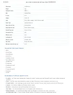
6. For connection of IN1~IN4, it is suggested that you connect the 4 inputs individually to the same type of deivce. The devices can be as follows: the rotary swtich,
the toggle switch, or the push switch.
7. When the Controller is damaged or lost, and you have already transferred the control function to an external control switch before, the product can be normally
operated. In other case, please purchase a new Controller, press the Include/Exclude Button three times to exclude the device, and then include the device with
the original installation steps, the device can be restored to normal operation. Please note that reincluding the product will reset the data to the default values. Use
this procedure only in the event that the network primary controller is missing or otherwise inoperable.
Inclusion/Exclusion
On factory default the device does not belong to any Z-Wave network. The device needs to be
added to an existing wireless network
to communicate with the
devices of this network. This process is called
Inclusion
.
Devices can also be removed from a network. This process is called
Exclusion
. Both processes are initiated by the primary controller of the Z-Wave network. This
controller is turned into exclusion respective inclusion mode. Inclusion and Exclusion is then performed doing a special manual action right on the device.
Inclusion
Include the R.G.B.W. color LED Dimmer intor the Z-Wave network, press service button 3 times in 2 seconds. If the device is properly include the green light will
remains on.
Exclusion
Exclude the Flush RGBW Dimmer into Z-Wave network, press 3 times in 2 seconds. If the device is proporly excluded, the green light will blink and data will be
reset to the factory default values.
Auto-Inclusion
Beside the standard inclusion this devices supports the so called
auto inclusion
. Right after powering up the device remains in inclusion state and can be
included by (any) gateway without further actions on the device itself. The auto inclusion mode will time out after some time.
Product Usage


