This is an overview only. Familiarize yourself with the manual and the manuals of
any connecting devices before installation. It is always recommended that
electronic equipment be installed by an experienced installer.
QK-A051T
BEFORE YOU LEAVE YOUR HOME:
You will need to input the Configuration information using a Windows system and configuration
tool before using A051T on water.
Ensure you can load the driver and configuration software through either CD or through internet
access (we advise you download the software to your Windows system before travelling to your
boat).
Drivers:
May automatically install to your device if it is running Windows 10. If not, it is
included on the FREE CD and as a download from www.quark-elec.com
INSTALLATION
1. Mounting: Consider your location…
Dry, sturdy location.
Ensure you have the correct length of cables Seal around any drill holes to prevent damage
to your equipment.
2. Connect your VHF Antenna
If you want to use one VHF antenna for both AIS and radio (or other purposes), then you will
need an active splitter. An active splitter will protect the A051T and your other VHF
equipment (VHF radio). If not, the two signals will significantly damage each device
connected, as well as reducing the signal.
If using two VHF antennas place them a good distance from each other. (at least 3 metres).
3. Connect your GPS antenna
GPS antenna is connected via the TNC female bulkhead connector. The GPS antenna should be
located outside where the sky is visible for best results.
4. Connect Power
The A051T uses 12V –24Vpower. This is connected via the POWER/NMEA cable.
Beware, do not swap Power+ (Red wire– 12-24V) and Power- (Black wire- GND) ,
Swapping these wires would damage your unit. Check all connections carefully.
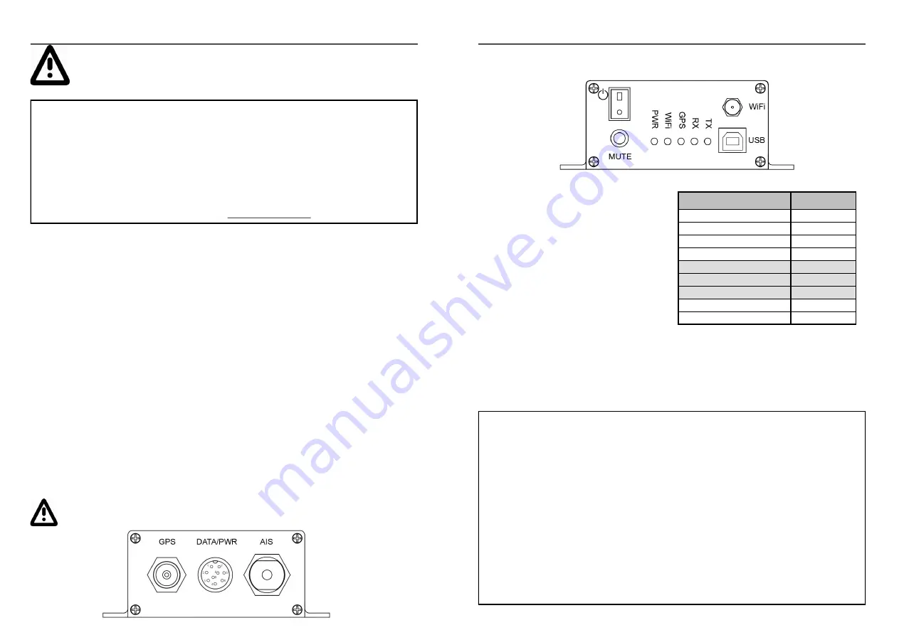
5. Once connected check the LED lights are Flashing green.
lights indicate a valid AIS or GPS
signal is being received by the A051T. (TX related to transmitted AIS, and RX to received AIS)
QK-A051T
The A051T contains two NMEA outputs:
1. NMEA 0183 RS422
2. NMEA 0183 RS232
Connect either or both outputs to a chart
plotter or other device of your choice.
7. Re-connect 12V power once all connections are correct.
Check LEDs are still working.
8. Connect your A051T to a Windows system for Configuration, using the provided USB cable.
Install the Configuration software (and drivers if needed), now you are ready to enter your con-
figuration information (see next page).
Pin name
Colour
Power+
Red
GND / Power-
Black
RS232 TX
White
GND for RS232 only
Gray
RS232 RX (reserved)
Purple
RS422 R+ (reserved)
Yellow
RS422 R- (reserved)
Orange
RS422 T+
Blue
RS422 T-
Green
6. Disconnect power
and connect NMEA output/s if desired.
9. WiFi output: to connect wirelessly you have three options:
Ad-hock WiFi:
The device is set to connect wirelessly in Ad-hoc mode (with no need for a router
or access point or any configuration).
On your device (phone, laptop etc.):
15 seconds after the A051T has powered up, you can
scan for a WiFi network with an SSID similar to ‘QK-A051xxxx’. Connect the device to ‘
QK-
A051xxxx
’ with the default password: ‘
88888888
’.
Chart software:
set the protocol as ‘
TCP
’, IP address as ‘
192.168.1.100’
and the port number
as ‘
2000
’ in the chart software.
Station mode WiFi settings
To change to Station mode (connecting through a router) or adjust other settings, you will do this
in the Configuration software. See the Configuration section of the manual.
WiFi on Standby:
you can turn of the WiFi transmission in the Configuration software if de-


