
14
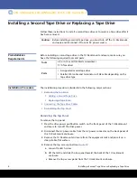
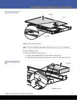
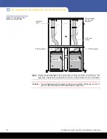
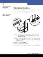
Installing a Second Tape Drive or Replacing a Tape Drive
LTO-3 (Model B), LTO-4 (Model B), LTO-5, LTO-6 and LTO-7
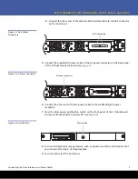
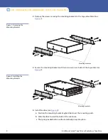
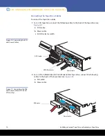
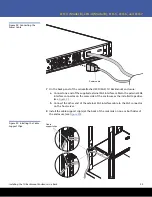
Figure 19 Connecting One
Drive on One SCSI Bus
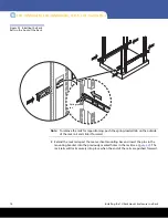
Note:
To prevent possible data errors, when there is only one drive on a SCSI bus, the
tape drive should be connected to the SCSI connector closest to the terminator.
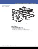
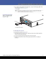
Caution:
To avoid damaging the equipment due to electrostatic discharge, be sure to
practice ESD procedures when handling the tape drive.
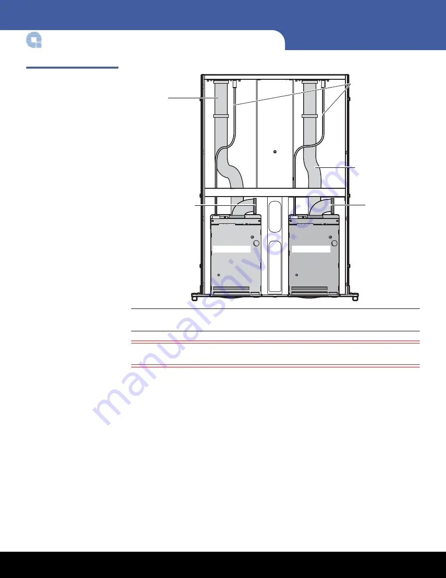
3
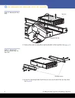
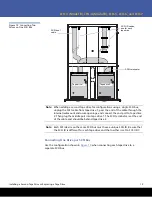
Tape drive 1
SCSI bus 1
cable
SCSI ID cables,
one for each
tape drive
Tape drive 2
SCSI terminator
SCSI bus 1
cable
SCSI terminator