


QuantAsylum QA450 User’s Manual
Page 7
DUT Power LED
This LED indicates if the high-side switch is enabled or not. If the LED is flashing
rapidly, then soft-start is in process.
If both the 8 and 4 ohm LEDs are flashing, then it means the QA450 has reached a thermal limit. This is
not harmful to the QA450. When this happens, the QA450 will open the relays automatically and ensure
the load inputs are removed from the internal load resistors.
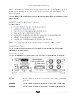
Current Sense Inputs
The QA450 uses an isolated Hall sensing device to measure the power supply DC. The positive terminal
of the amplifier
’s
DC power supply flows into the S+ pin on the front panel, is sensed by the Hall sensing
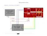
device, and then flows out of the S- terminal to the amplifier (see Appendix I Connection Diagram). The
Hall sensor used is an Allegro Micro ACS711, with +/- 15A of measurement range. On the QA450, only
positive current (from DC supply to the amp) are reported. If a negative current is measured, it is
clamped at 0 amps.
For the high-side PMOS switch to work, the DUT GND must be connected. Additionally, the voltage
controlled by the switch must be at least 5V (S+ to DUT GND) and not exceed 50V (S+ to DUT GND). If
the voltage is too low (less than 10-15V), the PMOS switch cannot be fully turned on. If the voltage is too
high (more than 50V) internal components may be overstressed and could fail. The QA450 is designed to
operate continuously at 50V and can withstand normal transients excursions above 50V.
The current sensing is not required to be used. For example, if you are testing Class D amplifier boards, it
might make sense to use the current sense and power the boards from a fixed external supply. But if
you are testing finished amplifiers that run from AC, then the DC measurement provided by the QA450
isn’t useful and can be skipped
.
ATTENTION! DO NOT CONNECT THE CURRENT SENSE CONNECTOR WHEN THE DUT LED IS ON!
Do not swap amplifier boards when the DUT LED is on!
If your power supply and amplifier both have massive capacitors, and you connect the amplifier while
the DUT power is enabled, then potentially hundreds or even thousands of amps can flow through the
high-side switch and cause it to fail as the charge is re-distributed
The Current Sense connector on the QA450 is a Molex 39536-0003. The mating connector is a Molex
39534-0003. This connector has a rating of 300V and 15A per pin.
Do not exceed the 10A RMS rating or 15A max rating of the Current Sense subsystem.
DUT Power Soft Start
When the DUT Power is activated, the DUT Power LED will flash rapidly for 1 second. This indicates that
soft-start is underway. During soft-start the DUT amplifier is connected to the high-side rail (S+) through
a 10 ohm resistor. This allows amplifiers with very large filter caps to charge at current l
evels that won’t
stress components in the power supply, the QA450 and the DUT amplifier. A large amplifier might have
10 mF of bulk capacitance. The RC time constant of the 10 mF and 10 ohm is 100 mS. Thus, the one-
second soft-start allows 10 time constants of soft-start to elapse before bypassing the soft-start resistor.
See the discussion below on


