


501440 Rev. J
5-1
FCO Type B Installation
5.
FCO Type B Installation
5.1
Fibre Channel Option (FCO) Type B Installation Considerations
5.1.1
Operating Environment
A TLS with the Fibre Channel Option is designed to operate in an ambient environ-
ment from 41
o
F to 95
o
F (5
o
C to 35
o
C), 20% to 80% relative humidity, and at altitudes
from -1000 to +10,000 feet. Moisture must not be allowed to condense inside the sys-
tem.
5.1.2
Ventilation
When selecting a location for the TLS, be sure to provide sufficient space behind the
unit to allow for cable connections. Also, be sure nothing will block the air intake at
the inlet air filters or the top air vent slots. The Fibre Channel Option is designed to
be rack mounted so be sure to allow sufficient space behind the unit to allow for cable
connections and space around it for air flow.
5.2
FCO Type B Interconnect Cabling
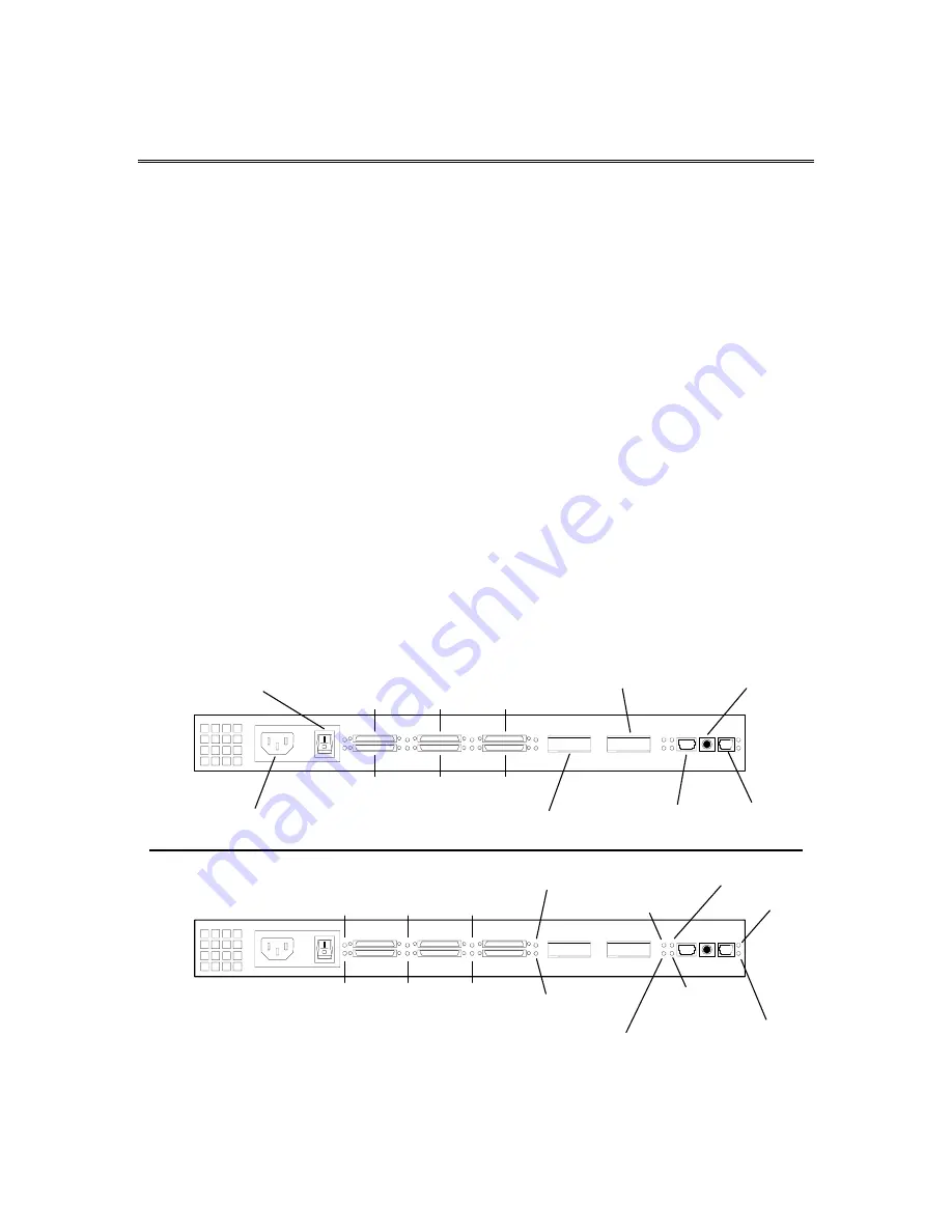
All the bridge/router interconnect and power cables are accessed at the rear of the
unit.
AC Power Receptacle
Power Switch
SCSI 0
SCSI 4
SCSI 2
SCSI 1
SCSI 5
SCSI 3
SERIAL
FAIL OVER
ETHERNET
FIBRE CHANNEL 0
FIBRE CHANNEL 1
SCSI 0
LED
SCSI 4
LED
SCSI 2
LED
SCSI 1
LED
SCSI 5
LED
SCSI 3
LED
AT LED 1
(Fibre Channel 1)
LK LED 1
(Fibre Channel 1)
AT LED 0
(Fibre Channel 0)
LK LED 0
(Fibre Channel 0)
ST LED
(Ethernet)
LK LED
(Ethernet)
ST LED
FT LED
Figure 5-1 Rear View of the Type B Fibre Channel Bridge/Router (FCO)