Model Q4P09
Installation, Operation and Maintenance
6
Rev 8/18/09
Q4P09-IOM-Q.doc
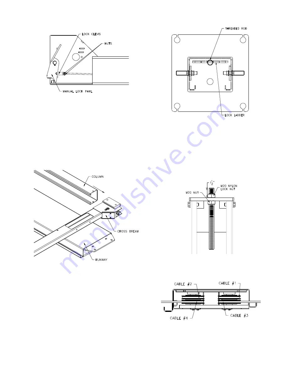
Fig 4 – Lock Clevis
C
OLUMNS
4) Disassembly each column assembly place the
columns close to each corner (column with the
power unit bracket goes at the front left column
per
Fig 1
).
5) With the runways spaced per
Fig 1
, lay the
cross beams on the runway per
Fig 5
below.
Place cardboard between the runway and
cross beam. Slide the column over the ends of
the slide blocks on the cross beam. Repeat for
each column.
Fig 5 – Column/Cross Beam Assembly
6) With help, stand up the front and rear
column/cross beam assemblies.
7) Reassembly the lock ladder to the top cap at
each column. Note: the lock ladder is offset
from the center of the threaded rod, and
orientate per
Fig 6
.
Fig 6
–
Locking Ladder Orientation
8) Adjust the lock ladder so about 1½” remains
sticking out of the top. Torque both bolts as
shown in
Fig 7
when ladder is properly
orientated. Note: When adjusting the lock
latter it maybe necessary to loosen or remove
the bolts holding the top cap to the column so
the bottom nut can be adjusted easily.
Fig 7 – Lock Ladder Assembly
9) Repeat for remaining three columns.
R
UNWAY
L
AYOUT
Fig 8 –
Power Runway 4-Stack
(rear view)


