Tighten set screw
Linkage control arm
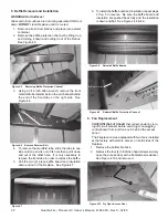
Figure 4.33 Linkage Control Arm Installed
D cut side of timer shaft must face
away from the Linkage Timer Arm
Remove Timer
Loosen Set Screw
Remove
2 screws
6. Remove the linkage arm and the spring from the
timer. See Figure 4.30.
Remove spring
Remove screw
Figure 4.30 Removal of Linkage Arm and Spring
7.
Loosen set screw on timer, remove two screws and
remove timer. See Figure 4.31.
Figure 4.31 Timer
8.
Install new timer using same two screws. It is very
important that the D cut side of the timer shaft is
facing the opposite side of the linkage timer arm.
See Figure 4.32.
Figure 4.32 D Cut on Shaft
9.
• Place linkage control arm over timer shaft and
tighten set screw, Figure 4.33.
10.
Rotate linkage control arm into final position. Note
that the D cut is now facing the linkage timer arm.
Re-attach the linkage timer arm and spring. See
Figure 4.34.
Figure 4.34 Reattach the Linkage Timer Arm
11.
Install the timer/leakage by inserting the timer in first
and slipping the linkage over the rod. See Figure
4.34.
Figure 4.34 Insert the Timer/Leakage
12.
Screw the timer to the air chamber. See Figure 4.35.
Screws
Figure 4.35 Screw Timer to Air Chamber
26
Quadra-Fire • Pioneer-II-C Owner’s Manual • 4184-900 • Rev C • 02/20


