15
TD-000487-00
K Series Service Manual
5. Top-box disassembly instructions
To reduce the number of pages in this service manual, all top-box K-Series loudspeakers have been combined into one
section. The K10 powered loudspeaker is used as an example for these generic disassembly and repair procedures. The K8
and K12 models are assembled nearly identical to the K10. Slight differences are as follows:
•
K8 does not have rubber feet on the side for floor monitor wedge use.
•
Pole-cup assembly is slightly different on each model
•
The K12’s high frequency transducer is not secured to the front of the baffle with screws. Instead, it’s all mounted behind
the waveguide with screws and washers.
For QSC part numbers, use “12. Component identification” on page 48 or “13. Exploded view drawings” on page 52.
5.1 Bucket of power
Removal
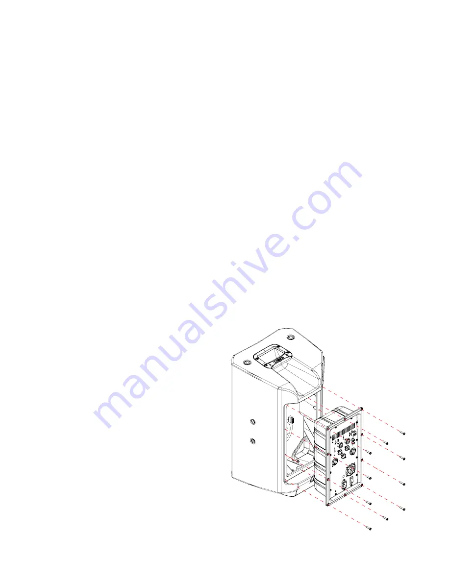
1. Remove the 10 screws along the outer perimeter of the BOP.
2. Partially remove the amplifier module out of the main enclosure as seen in Figure 5.1.
Note
: Occasionally the module will be stuck to the enclosure. Place a putty or butter knife between the enclosure and
edge of the module to pry the module out.
3. Detach the multi-pin molex connector from the read of the module.
4. The BOP can now be fully removed.
Installation
1. Verify all internal wiring. The positive and negative terminals of the LF and HF transducers should be securely connect-
ed. The molex connector should be inspected for loose wires.
2. Lay the speaker face-down on its front grille.
3. Connect the molex connector into the module.
4. Slowly drop the BOP down and align the holes along
the rim of the BOP to the holes on the enclosure.
5. Fasten the 10 screws that secure the BOP to the enclo-
sure, beginning with the corner screws.
Figure 5.1 - BOP removal from a top-box model
Содержание K8
Страница 2: ...2 QSC Audio Products LLC...


