7
TD-000477-01-A
Screens
Channel Configuration Screens
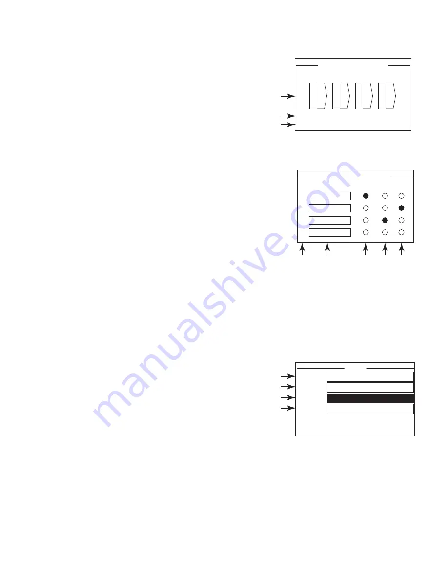
1. — Figure 16 is a graphic representations of the amplifier's output
CHANNEL CONFIGURATION. Inputs (Q) are from Q-SYS, outputs A–D
(E–H not shown) show the amplifier channels and their configuration.
2. Text indicating how many channels, and the output configuration.
For possible configurations refer to the Q-SYS help for the
amplifier components.
3. Status of the amplifier and Q-SYS design indicating the design and
amp are in sync.
Routable MIC/LINE Inputs
— Figure 17 shows the Routable MIC/LINE INPUTS screen for channels 1–4,
(channels 5–8 not shown) which displays the status of the physical MIC/LINE
INPUTS for the Q models.
This screen is not available on the Qn model amplifiers.
1. Input channels are identified numerically, 1–4 (and 5–8 not shown)
2.
nput Level
– is the Peak Input Level (dBFS) and is the same as displayed in
the Q-SYS Mic/Line Input component.
3.
Iuted
– when illuminated indicates that the Input is muted for the associated
channel. This is controlled by the Mute button on the Q-SYS Designer
Mic/Line Input component.
Input channels cannot be muted from the
amplifier interface.
4.
lip
– indicators illuminate when the input to the Mic/Line Input component is too high. Adjust the Preamp Gain on
the Mic/Line Input component in Q-SYS Designer.
5.
M12
– phantom power (+12V) is available for microphones (condenser) requiring the power. You can turn the
phantom power on/off in the Mic/Line Input component in Q-SYS Designer.
Status Screen
Refer to — Figure 18
1.
DTV T
– the hostname (network name) of the amplifier. A default
name is given at the factory, similar to the example. You may change
the name in the Q-SYS Configurator.
2.
DTS NA
– the name of the Q-SYS design currently running on
the amplifier. The amplifier must be contained in a running design
to operate.
3.
SRTRAS
– displays the current status of the amplifier both in text
and color. The following is a list of possible status colors, and some
example conditions.
•
PK
– green – audio is good, hardware is good.
•
ompromised
– orange – audio is good but a redundancy mechanism is active (one LAN down but the other is still
up) or a non-fatal hardware problem exists (fan speed, high temperature, low AC voltage, output load, amplifier is in
Protect mode, etc.)
•
Fault
– red – audio is not passing, or hardware is malfunctioning or mis-configured (amplifier power off, audio
streams broken, amplifier fault, loudspeaker short circuit, etc.)
•
nitializing
– blue – In the process of initialization, and design start. Audio is not passed.
— Figure 16 —
4 Channels: E F G H
Channel Configuration Locked to Design
Q E
Q F
Q G
Q H
CHANNEL CONFIGURATION
4 Channels: A B C D
Channel Configuration Locked to Design
Q A
Q B
Q C
Q D
CHANNEL CONFIGURATION
1
2
3
1
2
3
— Figure 17 —
ROUTABLE MIC/LINE INPUTS
INPUT LEVEL
MUTED
CLIP
P12
1
2
3
4
dB
dB
dB
dB
2
3
4
5
1
— Figure 18 —
STATUS
DEVICE:
DPAQ8CH-1234
DESIGN:
My Design Filename
STATUS:
OK
FIRMWARE:
6.1.00
1
2
3
4


