background image

User Manual

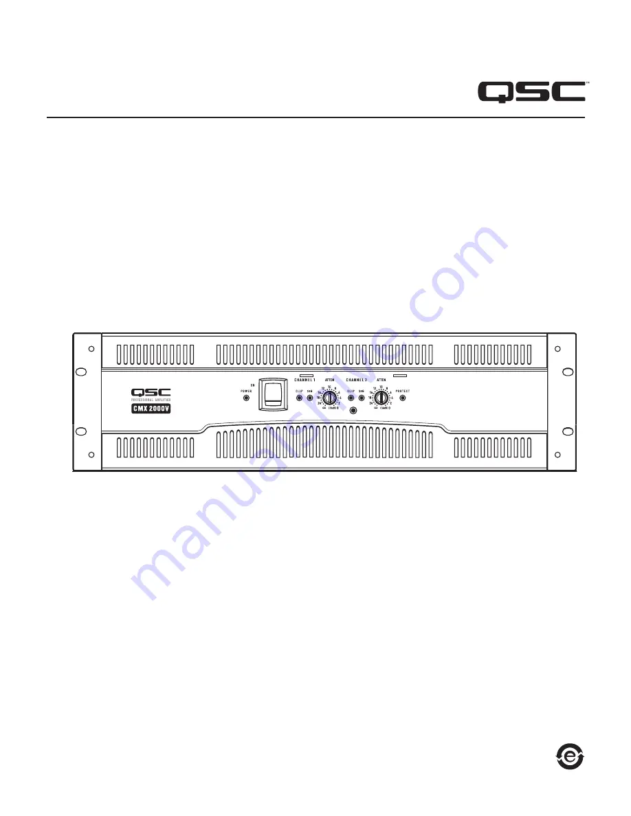
CMX 2000V Amplifier

CMX Series

*TD‑000323‑00*

TD‑000323‑00 

Содержание CMX2000V

Страница 1: ...User Manual CMX 2000V Amplifier CMX Series TD 000323 00 TD 000323 00 ...

Страница 2: ...nding type plug on the three pronged Edison style power cable The grounding plug has two blades and a grounding prong The third prong is provided for your safety If the provided plug does not fit your outlet consult an electri cian for the replacement of the obsolete outlet Do not cut off the grounding plug or use an adapter that breaks the grounding circuit This apparatus must be properly grounde...

Страница 3: ...ny product which has been subjected to misuse neglect accident improper installation or where the date code has been removed or defaced QSC shall not be liable for incidental and or consequential damages This warranty gives you specific legal rights This limited warranty is freely transferable during the term of the warranty period Customer may have additional rights which vary from state to state...

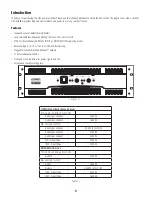
Страница 4: ...nced inputs XLR 6 3 mm TRS and barrier strip Pluggable terminal block and Speakon outputs 21 detent attenuation knobs Front panel LED indicators for power signal and clip Attenuation control security plate STEREO Mode Both channels driven FTC 20 Hz 20 kHz 0 1 THD 8 ohms per channel 1050 W 4 ohms per channel 1600 W EIA 1 kHz 1 THD 8 ohms per channel 1100 W 0 1 THD 4 ohms per channel 2000 W 2 ohms p...

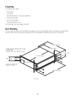
Страница 5: ...ifier User s manual Adhesive rubber feet for non rack mount applications Attenuation security plate Rear rack ear mounting kit IEC type detachable power cord Use the same type carton when shipping the amplifier Rack Mounting Use four screws and washers to mount the amplifier to the equipment rack rails To use the amplifier outside a rack attach the self adhesive rubber feet to the bottom Use the r...

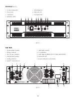
Страница 6: ...ut connectors 2 XLR input connectors 3 TRS 1 4 input connectors 4 Mode switches and settings 5 Cooling air inlet vents 6 Speakon output connectors 7 Terminal block connector 8 AC circuit breakers 9 Switch settings for PARALLEL INPUTS STEREO BRIDGE MONO 10 Serial number label 11 IEC power inlet power cord connector 7 8 9 10 11 1 2 3 4 5 6 Front Panel Figure 3 Back Panel Figure 3 Figure 4 ...

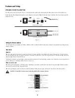
Страница 7: ... amount of overdrive To preserve as much of the program dynamics as possible limiting reduces the average program level until peaks barely clip The limiter only responds to actual clipping and automatically compensates for load and voltage variations Each channel has its own clip limiter and you can switch it on or off independently as shown in Figure 6 When to use it or not When driving full rang...

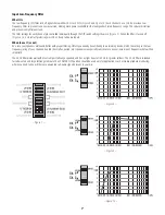
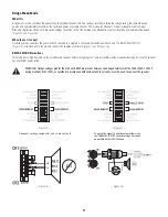
Страница 8: ...audio inputs When to use it or not As a rule your speakers will sound better with proper filtering Unless you already have filtering in a preceding device match the setting to the low frequency rating of your speakers Vented bass reflex ported etc speakers are especially sensitive to cone over excursion at frequencies below their rated limit The 50 Hz filter works well with most compact full range...

Страница 9: ...amping or other 2 channel modes In PARALLEL INPUTS mode you can use the other set of input connectors to carry the signal to other amplifiers Figure 12 This is often called a daisy chain When to use it Use the PARALLEL INPUTS mode when driving two speakers with one input signal This maintains separate control of gain filtering and limiting Note If you re using a balanced signal use only balanced p...

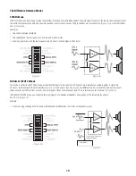
Страница 10: ...ositions 6 and 7 to BRIDGE MONO ON Figure 13 Use Channel 1 s inputs and connect the speaker as shown in Figure 15 and Figure 16 BRIDGE MONO Precautions This mode puts a high demand on the amplifier and speaker Excessive clipping may cause protective muting or speaker damage Be sure the speaker has a sufficient power rating WARNING Output voltages greater than 100 volts RMS are present between the ...

Страница 11: ...imilar to the STEREO mode except that the inputs for Channel 1 and Channel 2 are internally connected together A signal into Channel 1 jack drives both channels directly Figure 19 Use Channel 1 Input do not connect different sources to both channels Each channel s attenuation control still functions as usual and each channel feeds its own speaker load The dip switches are set as shown in Figure 20...

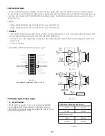
Страница 12: ...ands of watts into a single speaker AC current consumption will usually be higher Avoid excessive signal level and make sure the wiring and speaker can handle the power If the load is 4 ohms or less and prolonged overloads occur the amplifier will probably mute for several seconds during peaks and the circuit breaker may trip Do not use 2 ohm loads See the additional BRIDGE MONO mode warnings on p...

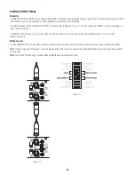
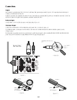
Страница 13: ...e 24 Unbalanced Inputs Connect the unused side Pin 3 of the balanced input to ground Pin 1 as shown in Figure 25 For STEREO operation use the inputs for both Channel 1 and Channel 2 For PARALLEL INPUTS or BRIDGE MONO operation use the Channel 1 input See the section on operating modes for more information To patch the audio signal to other amplifiers PARALLEL INPUTS and BRIDGE MONO modes only see ...

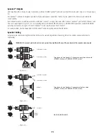
Страница 14: ...tions on page 9 Channel 2 Speakon carries only the output from Channel 2 For easier insertion use the newer style NL4FC Speakon connectors with quick lock thumb latches Speaker Cabling Larger wire sizes and shorter lengths minimize both loss of power and degradation of damping factor Do not place speaker cables next to input wiring WARNING To prevent electric shock do not operate the amplifier wit...

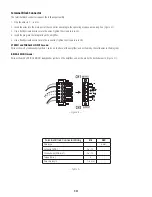
Страница 15: ...cle on the amplifier 5 Use a flat tip screwdriver to secure the connector Tighten the screws to 6 in lbs STEREO and PARALLEL INPUTS mode Wire as shown by loudspeaker symbols 1 and 2 on the back of the amplifier and as shown by the solid wires in the diagram Bridge MONO mode Wire as shown by BRIDGE MONO loudspeaker symbol on the amplifier and as shown by the dashed wires in Figure 31 Terminal Block...

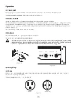
Страница 16: ...uation Settings should normally be made within the lower attenuation range The range above 14 on the attenuation scale should not be used for normal program levels as the input headroom could be exceeded but can be used for testing at reduced gain levels At the maximum attenuation setting the signal is com pletely cut off Figure 33 The maximum Voltage Gain for the CMX 2000V is 31 6 x 30 dB LED Ind...

Страница 17: ...hooting section Cool air enters the amplifier and rack Warm air exits the amplifier and rack Figure 35 Troubleshooting Problem No Sound Indication POWER indicator not lit Check the AC plug Also check the circuit breaker on the rear panel Confirm that the AC outlet works by plugging in another device If too many amplifiers are used on one outlet the building s circuit breaker may trip and shut off ...

Страница 18: ...eaker to locate the fault Indication CLIP LED not flashing This could be caused by a faulty speaker or loose connection Check the wiring and try another speaker The signal source may be clipping Keep the amplifier attenuation controls at mid point so that the source does not have to be overdriven Problem No channel separation Check the switch settings on the back of the amplifier Make sure the Par...

Страница 19: ...4Ω 120 VAC 230 VAC 13 9 A 7 A 26 9 A 13 5 A Frequency Response 20 Hz 20 kHz 1 dB dB 3 dB points 5 Hz and 50 kHz LF filter bypassed 8Ω Damping Factor 300 at 8Ω Input Impedance Ω 10 kΩ unbalanced 20 kΩ balanced Input Clipping 6 4 Vrms 18 dBu Cooling Continuously variable speed fan back to front air flow Connectors each channel Input Active balanced barrier strip XLR and 1 4 6 3 mm TRS tip and XLR pi...

Страница 20: ...simile Numbers Sales Marketing FAX 714 754 6174 Customer Service FAX 714 754 6173 World Wide Web www qscaudio com E mail info qscaudio com service qscaudio com 2010 QSC Audio Products LLC All rights reserved QSC and the QSC logo are registered trademarks of QSC Audio Products LLC in the U S Patent and Trademark office and other countries Speakon is a trademark of Neutrik All other trademarks are t...

Страница 21: ...Manuel d utilisation Amplificateur CMX 2000V Série CMX TD 000323 00 TD 000323 00 ...

Страница 22: ...re du câble d alimentation de style Edison à 3 broches Une fiche de terre a deux broches et une broche de terre La troisième broche assure la sécurité Si la fiche fournie n entre pas dans la prise consulter un électricien pour faire remplacer la prise obsolète Ne pas couper la fiche de terre et ne pas utiliser d adaptateur qui rompe le circuit de mise à la terre Par mesure de sécurité cet appareil...

Страница 23: ... garantie ne s étend à aucun produit qui a été soumis à une utilisation abusive un acte de négligence un accident une installation incorrecte ou un produit dont le code date a été retiré ou effacé QSC ne pourra être tenue pour responsable de dommages accessoires et ou indirects Cette garantie vous accorde des droits spécifiques Cette garantie limitée est librement cessible durant sa période de val...

Страница 24: ...E MONO mono pont Entrées équilibrées XLR TRS 6 3 mm et bornier à cloisons Bornier enfichable et sorties Speakon Boutons d atténuation à 21 crans Voyants du le panneau avant alimentation signal et limiteur Plaque de sécurité de commande d atténuation Mode STEREO deux canaux pilotés FTC 20 Hz 20 kHz à taux d harmonique THD 0 1 8 ohms par canal 1 050 W 4 ohms par canal 1 600 W EIA 1 kHz à THD 1 8 ohm...

Страница 25: ...ications de montage sans bâti Plaque de sécurité d atténuation Kit de pattes de fixation pour bâti arrière Cordon d alimentation détachable type CEI Utiliser le même type de carton pour renvoyer l amplificateur Installation sur bâti Utiliser quatre vis et rondelles pour installer l amplificateur aux coulisses à équipement du bâti Pour utiliser l amplificateur en dehors d un bâti attacher les pieds...

Страница 26: ...à cloisons 2 Connecteurs d entrée XLR 3 Connecteurs d entrée TRS 6 mm 4 Commutateur de mode et réglages 5 Bouches d arrivée d air de refroidissement 6 Connecteurs de sortie Speakon 7 Connecteur de bornier 8 Disjoncteurs 9 Réglages des commutateurs de mode PARALLEL INPUTS STEREO BRIDGE MONO 10 Étiquette de numéro de série 11 Entrée d alimentation CEI connecteur du cordon d alimentation 7 8 9 10 11 ...

Страница 27: ...arge Pour préserver au maximum la dynamique du programme l écrêtage réduit le niveau de programme moyen juste en dessous du niveau d écrêtage Le limiteur répond uniquement à une limitation réelle et compense automatiquement les variations de charge et de tension Chaque canal a son propre limiteur d amplitude indépendamment activable ou désactivable comme illustré à la figure 6 Quand l utiliser ou ...

Страница 28: ...ser ou non En règle générale vos haut parleurs donneront un meilleur son avec un filtrage adéquat Sauf si vous avez déjà un filtre dans un appareil précédent faire correspondre le réglage à la basse fréquence nominale de vos haut parleurs Les haut parleurs à évent bass reflex résonnant etc sont surtout sensibles à une course excessive de la membrane à des fréquences inférieures à leur limite nomin...

Страница 29: ...de PARALLEL INPUTS vous pouvez utiliser l autre jeu de connecteurs d entrée pour transporter le signal aux autres amplificateurs Figure 12 On parle souvent de connexion en guirlande Quand l utiliser Utiliser le mode PARALLEL INPUTS pour piloter les deux haut parleurs avec un signal d entrée Ceci permet de maintenir les commandes de gain filtrage et limitation séparées Remarque Si un signal équilib...

Страница 30: ...gure 13 Utiliser les entrées du canal 1 et brancher le haut parleur comme indiqué à la figure 15 et à la figure 16 Précautions liées au mode BRIDGE MONO Ce mode sollicite fortement l amplificateur et le haut parleur Un écrêtage excessif peut causer une sourdine de protection ou l endommagement du haut parleur S assurer que le haut parleur affiche une puissance nominale suffisante AVERTISSEMENT Des...

Страница 31: ...ceci près que les entrées du canal 1 et du canal 2 sont interconnectées Un signal dans la prise du canal 1 pilote directement les deux canaux Figure 19 Utiliser l entrée du canal 1 ne pas brancher différentes sources aux deux canaux La commande d atténuation de chaque canal fonctionne toujours comme d habitude et chaque canal alimente la charge de son propre haut parleur Les commutateurs DIP sont ...

Страница 32: ...n un haut parleur La consommation de courant sera généralement supérieure Éviter un niveau de signal excessif et s assurer que le câblage et le haut parleur peuvent gérer la puissance Si la charge est de 4 ohms ou moins et que des surcharges prolongées se produisent l amplificateur se mettra en sourdine pendant quelques secondes probablement durant les pics et le disjoncteur pourra se déclencher N...

Страница 33: ... bornier à cloisons Figure 24 Entrées déséquilibrées Brancher l extrémité inutilisée Broche 3 de l entrée équilibré sur la terre Broche 1 comme à la figure 25 En mode STEREO utiliser les entrées pour le canal 1 et pour le canal 2 En mode PARALLEL INPUTS ou BRIDGE MONO utiliser l entrée du canal 1 Pour des informations complémentaires voir la section sur les modes opératoires Pour câbler le signal ...

Страница 34: ...rte uniquement la sortie du canal 2 Pour une insertion plus facile utiliser le nouveau style de connecteurs NL4FC Speakon avec des clenches à verrouillage rapide Câblage des haut parleurs Les câbles de plus gros calibre et plus courts minimisent la perte de puissance et la dégradation du facteur d amortissement Ne pas placer les câbles de haut parleur à côté du câblage d entrée WARNING Pour éviter...

Страница 35: ... plate pour fixer les connecteur Serrer les vis à 0 67 Nm Modes STEREO et PARALLEL INPUTS Câbler comme illustré par les symboles de haut parleur 1 et 2 à l arrière de l amplificateur comme illustré par les fils pleins sur le diagramme MODE BRIDGE MONO Câbler comme illustré par le symbole de haut parleur BRIDGE MONO sur l amplificateur comme illustré par les fils en pointillés à la figure 31 Câblag...

Страница 36: ...é d atténuation Les réglages devraient nor malement être effectués dans la gamme d atténuation basse La gamme au dessus de 14 sur l échelle d atténuation ne doit pas être utilisée pour les niveaux de programme normaux dans la mesure où la marge de sécurité d entrée risque d être dépassée mais elle est utilisable pour les tests à niveaux de gain réduits Au réglage d atténuation maximum le signal es...

Страница 37: ...cas voir la section Dépannage L air frais entre dans l amplificateur et dans le bâti L air chaud sort de l amplificateur et du bâti Figure 35 Dépannage Problème Pas de son Indication Voyant POWER allumé Vérifier la fiche d alimentation Vérifier aussi le disjoncteur sur le panneau arrière Confirmer que la prise secteur fonctionne en branchant un autre appareil dessus Si trop d amplificateurs sont u...

Страница 38: ... Indication Le voyant CLIP ne clignote pas Ceci peut être causé par un haut parleur défectueux ou un branchement mal établi Vérifier le câblage et essayer avec un autre haut parleur La source du signal pourra être écrêtée Garder les commandes d atténuation de l amplificateur à mi distance pour que la source n ait pas à être annulée Problème Pas de séparation des canaux Vérifier les réglages des co...

Страница 39: ...onse en fréquence 20 Hz 20 kHz points 3 dB 1 dB 5 Hz et 50 kHz filtre passe bas contourné 8 Ω Facteur d amortissement 300 à 8 Ω Impédance d entrée Ω 10 kΩ non équilibré 20 kΩ équilibré Écrêtage d entrée 6 4 Vrms 18 dBu Refroidissement Ventilateur à vitesse variable continu circulation d air arrière avant Connecteurs chaque canal Entrée équilibrée active bornier à cloisons XLR et 6 3 mm extrémité T...

Страница 40: ...entes Marketing 714 754 6174 Fax Service clientèle 714 754 6173 Site Web www qscaudio com Courriel info qscaudio com service qscaudio com 2010 QSC Audio Products LLC Tous droits réservés QSC et le logo QSC sont des marques de QSC Audio Products LLC déposées auprès de l U S Patent and Trademark Office et dans d autres pays Speakon est une marque commerciale de Neutrik Toutes les autres marques de c...

Страница 41: ...Benutzerhandbuch Verstärker CMX 2000V Serie CMX TD 000323 00 TD 000323 00 ...

Страница 42: ...r besitzt zwei Stifte und einen Erdungspol nur für USA Kanada Der dritte Stift dient der Sicherheit Wenn der im Lieferumfang enthaltene Stecker nicht in Ihre Steckdose passt ist diese veraltet und muss von einem Elektriker ersetzt werden Den Erdungsstift nicht abschneiden und keinen Adapter verwenden der den Erdungsschaltkreis unterbricht Dieses Gerät muss zu Ihrer Sicherheit ordnungsgemäß geerdet...

Страница 43: ...en Herstellungsdefekt zu erkennen gibt Diese Garantie erstreckt sich auf keine Produkte die einer unsachgemäßen oder fahrlässigen Behandlung Unfällen oder einer unvorschriftsmäßigen Installation unterlagen oder deren Datumscode entfernt oder unkenntlich gemacht wurde QSC ist für keine Neben und oder Folgeschäden haftbar Diese Garantie gewährt Ihnen bestimmte Rechte Diese beschränkte Garantie ist w...

Страница 44: ...INGANGS oder MONO BRÜCKEN Betrieb Symmetrische Eingänge XLR 6 3 mm 1 4 TRS und Barrier Strip Steckbare Klemmleiste und Speakon Ausgänge Dämpfungsregler mit 21 Rastpositionen LED Frontanzeigen für Strom Netz Signal und Clip Dämpfungsregler Sicherheitsplatte STEREO Modus beide Kanäle angesteuert FTC 20 Hz 20 kHz bei 0 1 THD 8 Ohm pro Kanal 1050 W 4 Ohm pro Kanal 1600 W EIA 1 kHz bei 1 THD 8 Ohm pro ...

Страница 45: ...en die keinen Rack Einbau vorsehen Dämpfungssicherheitsplatte Rackeinbau Montagewinkel Kit zur Befestigung an der Verstärkerrückseite Abnehmbares IEC Netzkabel Verwenden Sie zum Verschicken des Verstärkers den gleichen Karton Rack Einbau Verwenden Sie zur Befestigung des Verstärkers an den Geräte Rack Schienen vier Schrauben und Unterlegscheiben Wenn der Verstärker nicht in einem Rack montiert wer...

Страница 46: ...2 XLR Eingangsanschlüsse 3 TRS 1 4 Eingangsanschlüsse 4 Betriebsartenschalter und einstellungen 5 Belüftungsschlitze 6 Speakon Ausgangsanschlüsse 7 Klemmleistenanschluss 8 AC Trennschalter 9 Schaltereinstellungen für PARALLELEINGÄNGE STEREO BRÜCKEN MONO 10 Seriennummernetikett 11 IEC Stromeingang Netzkabelanschluss 7 8 9 10 11 1 2 3 4 5 6 Frontplatte Abbildung 3 Rückplatte Abbildung 3 Abbildung 4 ...

Страница 47: ...n Um die Programmdynamik so weit wie möglich zu erhalten wird der durchschnittliche Programmpegel durch die Begrenzung nur so weit reduziert dass die Wellenspitzen minimal geklippt werden Der Begrenzer spricht nur auf ein tatsächliches Clipping an und kompensiert Last und Spannungsschwankungen automatisch Jeder Kanal verfügt über seinen eigenen Clip Limiter der unabhängig und wahlweise zu und abge...

Страница 48: ...nsatz Generell klingen Ihre Lautsprecher bei richtiger Filterung auch besser Falls nicht schon an anderer Stelle eine entsprechende Filterung stattgefunden hat stellen Sie die Filterung entsprechend der Niederfrequenzleistung Ihrer Lautsprecher ein Belüftete Lautsprecher z B Bassreflex mit Öffnungen usw sind ausgesprochen empfindlich gegen zu große Auslenkungen der Membran unterhalb des spezifizie...

Страница 49: ...Modus PARALLELEINGÄNGE können Sie zum Übertragen des Signals an andere Verstärker die andere Eingangsanschlussgruppe verwenden Abbildung 12 Dies wird häufig als Verkettung bezeichnet Einsatz Verwenden Sie den PARALLELEINGANGS Modus wenn Sie zwei Lautsprecher mit einem einzigen Eingangssignal ansteuern Dadurch wird eine separate Steuerung von Verstärkung Filterung und Spitzenbegrenzung aufrechterha...

Страница 50: ...en Lautsprecher unter Verwendung der Eingänge von Kanal 1 wie in Abbildung 15 und Abbildung 16 dargestellt an Vorsichtsmaßnahmen im MONO BRÜCKEN Modus Diese Betriebsart stellt hohe Anforderungen an Verstärker und Lautsprecher Ein übermäßiges Clipping kann zu einer Schutzabschaltung aber auch zu Lautsprecherbeschädigungen führen Stellen Sie sicher dass der Lautsprecher die zu erwartenden Leistungen...

Страница 51: ...änge für Kanal 1 und Kanal 2 intern zusammengeschaltet sind Ein Signal in der Kanal 1 Buchse steuert beide Kanäle direkt an Abbildung 19 Verwenden Sie den Kanal 1 Eingang Schließen Sie keine verschiedenartigen Quellen an beiden Kanälen an Der Dämpfungsregler eines jeden Kanals funktioniert weiter ganz normal und jeder Kanal versorgt seinen eigenen Lautsprecher separat Die DIP Schalter sind so eing...

Страница 52: ...cher abgegeben werden Die Wechselstromaufnahme ist normalerweise höher Vermeiden Sie überhohe Signalpegel und achten Sie darauf dass die Verkabelung und der Lautsprecher für diese hohe Leistung ausgelegt sind Bei Lasten von maximal 4 Ohm und zu langen Übersteuerungen kann der Fall eintreten dass sich der Verstärker bei der Erzeugung von Wellenspit zen abschaltet und der Trennschalter aktiviert wir...

Страница 53: ...ung 24 Asymmetrische Eingänge Schließen Sie die ungenutzte Seite Pin 3 des symmetrischen Eingangs am Erdungsstift Pin 1 an siehe Abbildung 25 Verwenden Sie für den STEREO Betrieb die Eingänge für Kanal 1 und Kanal 2 und für den PARALLELEINGANGS oder MONO BRÜCKEN Betrieb den Kanal 1 Eingang Weitere Informationen sind im Abschnitt mit der Beschreibung der verschiedenen Betriebsarten enthalten Um das...

Страница 54: ...f Seite 9 Die Kanal 2 Speakon Buchse überträgt nur das Ausgangssignal von Kanal 2 Um ein leichteres Anschließen zu ermöglichen verwenden Sie die neueren NL4FC Speakon Anschlüsse mit schnell verriegelnden Daumensicherungen Lautsprecherverkabelung Kabel mit größeren Durchmessern und kürzere Kabel minimieren Leistungsverluste und eine Verschlechterung des Dämpfungsfaktors Verlegen Sie keine Lautsprec...

Страница 55: ...Die Verbindung mit einem Flachschraubenzieher sichern Die Schrauben auf 0 68 Nm anziehen STEREO und PARALLELEINGANGS Modus Die Verdrahtung gemäß den Lautsprechersymbolen 1 und 2 auf der Rückseite des Verstärkers und gemäß den durchgehenden Leitern im Diagramm vornehmen MONO BRÜCKEN MODUS Die Verdrahtung gemäß dem MONO BRÜCKEN Lautsprechersymbol am Verstärker und gemäß den gestrichelten Leitern in ...

Страница 56: ...Dämpfungsbereich bewegen Der Dämpfungsbereich oberhalb von 14 sollte für normale Programmpegel nicht verwendet werden da der Eingangs Headroom überschritten werden könnte er kann jedoch zu Testzwecken bei reduzierten Verstärkungspegeln verwendet werden Bei der maximalen Dämpfungseinstellung wird das Signal völlig abgeschnitten Abbildung 33 Die maximale Spannungsverstärkung für den CMX 2000V beträg...

Страница 57: ...ehebung Kalte Luft strömt in den Verstärker und das Rack Warme Luft strömt aus dem Verstärker und dem Rack Abbildung 35 Fehlerbehebung Problem Kein Ton Symptom NETZ Anzeige leuchtet nicht Netzstecker überprüfen Außerdem den Trennschalter auf der Rückplatte überprüfen Durch Anschließen eines anderen Geräts überprüfen ob die Steckdose ordnungsgemäß funktioniert Wenn zu viele Verstärker an derselben ...

Страница 58: ...ren Symptom CLIP LED blinkt nicht Dieses Symptom kann von einem defekten Lautsprecher oder einer losen Verbindung verursacht werden Die Verkabelung überprüfen und einen anderen Lautsprecher ausprobieren An der Signalquelle kann eine Übersteuerung Clipping vorliegen Die Verstärker Dämpfungsregler auf einen mittleren Wert einstellen sodass die Quelle nicht übersteuert werden muss Problem Keine Kanal...

Страница 59: ... VAC 230 VAC 13 9 A 7 A 26 9 A 13 5 A Frequenzgang 20 Hz 20 kHz 1 dB dB 3 dB Punkte 5 Hz und 50 kHz Tiefpassfilter umgangen 8 Ω Dämpfungsfaktor 300 bei 8 Ω Eingangsimpedanz Ω 10 kΩ asymmetrisch 20 kΩ symmetrisch Eingangsclipping 6 4 V eff 18 dBu Kühlung Stufenlos einstellbarer Lüfter Luftströmung von hinten nach vorne Anschlüsse pro Kanal Eingang aktiv symmetrisch Barrier Strip XLR und 1 4 6 3 mm ...

Страница 60: ...Verkauf und Marketing 1 714 754 6174 Kundendienst Fax 1 714 754 6173 Internet www qscaudio com E Mail info qscaudio com service qscaudio com 2010 QSC Audio Products LLC Alle Rechte vorbehalten QSC und das QSC Logo sind eingetragene Marken von QSC Audio Products LLC und beim Patent und Markenamt der USA und anderer Länder angemeldet Speakon ist eine Marke von Neutrik Alle anderen Marken sind Eigent...

Страница 61: ...用户手册 CMX 2000V 放大器 CMX 系列 TD 000323 00 TD 000323 00 ...

Страница 62: ...产生热量 7 不要将本产品安装在会产生热量的热源 如散热器 热调节装置 炉子或其他设备 包括放大器 附近 8 请勿使 Edison 型电缆上的三爪接地插头的安全性失效 接地插头有两个叶片和一个接地爪 这个接地爪用来保 证您的安全 如果所提供的插头和您的插座不匹配 请向电工咨询了解如何更换该旧插座 请勿切断接地插头或使 用未接地的适配器 为保证您的安全 请确保此设备良好接地 9 请避免踩踏或挤压电线 尤其要注意插头 电源插座以及设备引出处的部分 10 电器耦合器是交流电源的断路设备 安装后应保持随时可用 11 仅限使用 QSC Audio Products LLC 指定的附件或配件 12 仅限使用随本设备或由 QSC Audio Products LLC 出售的硬件 托架和元件 13 在雷暴天气下或长时间不用时 请断开本设备的电源连接 14 应由合格人员进行维护 如果本设备损坏 如遇到电源线...

Страница 63: ...工厂或 任一授权维修点 预付运费并附带购买证明 即销售收据 复印件 此质保协议规定 退回的产品必须经我们检查断 定是否存在制造缺陷 本质保不适用于任何因误用 疏忽 意外或不正确安装导致损坏的产品或日期编码被去掉或破 损的产品 QSC 不对意外和 或间接发生的损坏承担责任 此质保赋予您特定的法律权力 此有限质保在保修期内可 自由转让 某些用户可能会拥有一些额外的权利 具体取决于其所在的州 此有限质保不适用于为出口或不在美国销售而生产的产品 产品上缺少序列号 或者从非授权销售商处购买此产品 将失去此有限质保 此质保会定期更新 如需最新版本的 QSC 质保声明 请访问 www qscaudio com 联系我们 800 854 4079 或访问我们的网站 www qscaudio com 版权所有 2010 QSC Audio Products LLC QSC 是 QSC Audio Produ...

Страница 64: ...阻挡跨接片 可插接线盒与 Speakon 输出 21 掣子衰减旋钮 用于指示电源 信号和削波的前面板 LED 指示灯 衰减控制安全板 立体声模式 双声道驱动 FTC 20 Hz 20 kHz 0 1 THD 每声道 8 欧姆 1050 W 每声道 4 欧姆 1600 W EIA 1 kHz 1 THD 每声道 8 欧姆 1100 W 0 1 THD 每声道 4 欧姆 2000 W 每声道 2 欧姆 2500 W 70V 直接驱动 2500 W 100V 直接驱动 1000 W 桥式单声模式 FTC 20 Hz 20 kHz 0 1 THD 8 欧姆 3200 W EIA 1 kHz 1 THD 8 欧姆 3600 W 4 欧姆 5000 W 0 1 THD 140V 直接驱动 5000 W 100V 直接驱动 3600 W 图 1 表 1 ...

Страница 65: ...5 8 402 mm 2 60 66 mm 槽口高 0 40 深 0 50 1 0 x 1 2 cm 孔的垂直中线距后沿 0 40 10 2 cm 孔尺寸 0 25 x 0 47 06 4 x 11 9 mm 图 2 拆包 出厂包装箱内包括以下内容 CMX 放大器 用户手册 粘性橡胶脚垫 用于非机架式安装 衰减控制安全板 后机架柄安装件 IEC 型可分离电源线 运送放大器时使用同一类型的包装箱 机架安装 用四颗螺丝和垫圈将放大器安装到设备机架导轨上 要在机架外使用放大器 需在底部装上自粘性橡胶脚垫 使用后 架柄支撑件来支撑放大器的后部以方便携带 请参考 图 2 进行计划 ...

Страница 66: ...件 5 削波和信号 LED 6 保护模式 LED 7 安全板螺钉 1 1 2 3 4 4 5 6 5 7 1 阻挡跨接片输入连接器 2 XLR 输入连接器 3 TRS 1 4 输入连接器 4 模式开关与设定 5 冷却进风口 6 Speakon 输出接头 7 接线盒连接器 8 交流电断路器 9 并行输入 立体声 桥式单声的开关设置 10 序列号标示 11 IEC 电源入口 电源线连接器 7 8 9 10 11 1 2 3 4 5 6 前面板 图 3 后面板 图 3 图 4 ...

Страница 67: ...限制器 作用 当音频信号驱动的放大器输出电路超过其电源容量时 它将削减波峰 使波形变平 削波限制器可检测到此情况并降 低增益 以尽量减少过载量 为了尽可能多地保留项目动态 削波限制会减少平均项目级别 直至波峰平滑切削 限制器只对实际的削波作出响应 并自动对负载和电压变化进行补偿 每个声道都有自己的削波限制器 可以独立地 打开或关闭 如 图 6 中所示 何时使用 或不使用 驱动全频程扬声器时 削波限制可减少由低音过载所引起的高频失真 还能使频率较高的驱动器免受过度超速驱动和 苛刻的削减谐波损害 驱动低音扬声器时 有些用户无限制地任放大器削波 因为它会给予鼓声和类似的声音额外的 重音 注意 在双放大器系统中 过度限制会影响频率平衡 衰减板安装槽口 2 衰减板 衰减板随附螺钉 衰减板未安装 衰减板已安装 图 5 图 6 ...

Страница 68: ...大器超 载 每个声道的滤波器设置由 DIP 开关设置独立控制 如 图 7 所示 当滤波器关闭时 图 8 5 Hz 滚降可防止 DC 或较深的亚音频输入 何时使用 或不使用 通常情况下 您的扬声器如果滤波适当 将能更好地发音 除非之前的设备中已有过滤 否则请将设置与扬声器的低 频级别匹配 当频率低于额定限制时 通风 低音反射 带孔等 的扬声器对锥形扬声器过度偏移尤其敏感 对于大多数小巧的全频程扬声器来说 50 Hz 的滤波器能很好工作 有时甚至能达到 100 Hz 30 Hz 滤波器用于超 低音扬声器和大的全频程机柜 LF 滤波器关 位置应仅用于如录音棚回放监控的应用程序 您需要了解混音中是否 存在不想要的亚音频信号 图 7 图 8 图 9 图 10 ...

Страница 69: ...来驱动其自身的扬声器负载 将开关位置 4 和 5 设置为 并行输入 使输入成对 图 11 对于立体声 双放大器或其他双声道模式 请将开 关拨至 立体声 处 在 并行输入 模式中 您可以使用另一组输入连接器将信号携带到其他放大器 图 12 这通常称为 菊链 何时使用 当使用一个输入信号驱动两个扬声器时使用 并行输入 模式 这样便可保持对增益 滤波以及限制的单独控制 注 如果您正使用平衡信号 请仅使用平衡连接线缆 因为哪怕只有一根不平衡线缆 也会使整个信号链失去平衡 甚 至可能产生嗡嗡声 注 向放大器输送两个单独的信号时 请关闭 并行输入 开关 图 11 图 12 ...

Страница 70: ...4 何时使用 或不使用 使用桥式单声模式将两个声道的功率传送到一个 8Ω 或 4Ω 的负载 将开关 6 和 7 的位置设置为桥接模式开 图 13 使用声道 1 的输入 并连接扬声器 如 图 15 和图 16 所示 桥式单声模式注意事项 此模式下的放大器与扬声器均高负荷运转 过度的削波可能会产生防御性的静音或导致扬声器损坏 请确保扬声器有 足够的额定功率 警告 大于 100 伏特 RMS 的输出电压均可用于 CMX 2000V 的桥接终端之间 根据国家标准以及地方标准中 的指令 必须用 CLASS 3 接线方法 NEC 1999 连接扬声器 要将信号添加到其他放大器 请使用 并行输入 模式中所述的 并行输入 开关设置 声道 2 设置 开关 8 和 10 均设为关闭 图 13 图 14 图 15 图 16 至扬声器 ...

Страница 71: ...的单声信号 如主混音和监听混音 双放大操作 在声道 1 中使用低频 而在声道 2 中使用高频 并行输入模式 此模式类似于立体声模式 但是声道 1 和声道 2 的输入是内部相连 到声道 1 插孔中的信号可直接驱动两个声道 图 19 使用声道 1 输入 不要将不同的源连接到两个声道 每个声道的衰减控件仍像往常一样工作 并且每个声 道输送其各自的扬声器负载 DIP 开关如 图 20 中所示设置 在并行输入模式中 您可以使用所剩输入插孔中的任一个 将输入信号添加到其他放大器中 请参见 图 19 中的 Ch 2 示例 一个单声信号驱动两个声道 每个扬声器系统包含独立的衰减控件 图 17 图 18 信号输入 无输入 可用于菊链其他放 大器 放大器 2 图 19 图 20 ...

Страница 72: ...驱动一个 4 欧姆扬声器 注意事项 您可以通过桥式单声模式将成千上万瓦特驱动到一个扬声器中 AC 电流消耗通常会更高 避免过度信号电平 并 确保接线和扬声器能在该功率下正常工作 如果负载为 4 欧姆或更少 并出现长期超载的情况 则放大器将可能在出现峰值时静音几秒钟 而且断路器可能会 出错 请勿使用 2 欧姆负载 请参见第 9 页上的其他桥式单声模式注意事项 将声道 2 DIP 开关 8 和 10 设置为关闭 图 21 图 22 图 23 立体声模式 双声道驱动 70 V 2500 W 100 V 1000 W 桥式单声模式 70 V 5000 W 100 V 3600 W 分布式常量电压输出 70 100 伏特操作 CMX 2000V 可在立体声模式或桥式单声 式下执行 70 伏特 或 100 伏特操作 请参考前面关于桥式单声模式的部分 进行正确的设置配置 请参考 表 2 获取这些模式的功...

Страница 73: ...情况 信号的源 阻抗应低于 600 欧姆 平衡输入 使用 XLR 或 6 3 mm TRS 输入插孔或阻挡跨接片 图 24 非平衡输入 将平衡输入的不使用的端 引脚 3 接地 引脚 1 如 图 25 所示 对于立体声操作 请使用声道 1 与声道 2 的输入 对于并行或桥式单声操作 请使用声道 1 输入 如需更多信息 请参见介绍操作模式的部分 要将音频信号添加到其他放大器 仅在 并行输入 模式和 桥式单 声 模式下 请参见第 8 11 页上有关使用 并行输入 的说明 以下三个连接的任 一个 XLR 非平衡跳线引脚 1 至引脚 3 引脚 1 接地 引脚 2 引脚 3 图 24 图 25 平衡 非平衡 接地 倒相输入 同相输入 接地 同相输入 图 26 图 27 ...

Страница 74: ... 道 2 输出信号 图 29 因而特别适用于 并行输入 双放大器 或 桥式单声 操作 请参见第 9 页上的 桥式单声 操作注意事项 声道 2 Speakon 仅传送来自声道 2 的输出 请使用新款的 NL4FC Speakon 连接器 该连接器拥有快速锁定的指按栓 可以更方便地进行插接 扬声器布线 更粗的电缆和更短的长度能使功率损耗和阻尼因数的降低最小 不要使扬声器电缆靠近输入线缆 警告 为避免电击 请勿在扬声器电线的导体暴露在外时操作放大器 2 个声道 2 个 Speakon 连接器 每个连接器使用两根电线 立体声 双放大器或并行输入模式 2 个声道 一个使用 4 根电线的 Speakon 连接器 立体声 双放大器或并行输入模式 桥式单声模式 至声道 1 扬声器 至声道 2 扬声器 至声道 1 扬声器 至声道 2 扬声器 声道 1 声道 2 至扬声器 图 28 图 29 图 30 ...

Страница 75: ...参见 图 31 3 使用平头螺丝刀将这些电线固定就位 将螺钉拧紧到 6 in lbs 4 将插头插入放大器上的插座 5 使用平头螺丝刀将连接器固定就位 将螺钉拧紧到 6 in lbs 立体声和并行输入模式 根据放大器后面的喇叭符号 1 和 2 并按图表中实线所示进行接线 桥式单声模式 根据放大器上的 桥式单声 喇叭符号并按 图 31 中的虚线所示进行接线 接线盒连接器接线 UL IEC 电线长度范围 6 mm2 实心线 AWG 28 10 绞线 AWG mm2 28 10 扭矩 lb in 6 电线剥离长度 7 8 mm 图 31 表 3 ...

Страница 76: ...32 衰减控件 顺时针转动衰减控件可减小衰减 逆时针转动则增大衰减 衰减控件以 至 0 顺时针 之间的数字增量标记 表示衰减量 正常情况下 应在较低衰减范围内进行设置 高于衰减级别 14 的范围不能用于正常程序电平 因为输入净空可能被超过 但可在降低增益电平下测试 在最大衰 减设置 处 信号完全中断 图 33 CMX 2000V 的最大电压增益为 31 6 x 30 dB LED 指示灯 大约在全功率的 0 1 时 绿色 LED 信号指示灯亮起 过载时 红色 LED 削波指示灯会闪动 正在削波 注意 持续高功率操作可能会激活热防护电路 而使得放大器停止运作 防护指示灯全亮 放大器充分冷却 后 操作会重新开始 如果两个后面板断路器都错误 防护指示灯将不会亮 请参见第 16 17 页中的 故 障排除 图 32 图 33 图 34 亮起 ...

Страница 77: ...单声 模式可使放大器的输出阻抗加倍 4 欧姆是最小负载阻抗 大幅度削波可能导致静音 如 果出现此情况 请参考 故障排除 一节 冷风进入放大器和机架 热风从放大器和机架流出 图 35 故障排除 问题 没有声音 现象 电源指示灯未亮 检查交流插头 还需检查后面板上的断路器 通过插入另一个设备 确认交流电源插座可用 如果在一个插 座上使用过多放大器 大厦的断路器可能会断开并关闭电源 桥式单声模式中的过载可能导致放大器关闭数秒 检查负载阻 抗 至少 4Ω 或降低信号水平 如果放大器经常关闭 则可能是内部出现严重故障 请关闭放 大器 断开交流电源 由合格的技术人员对放大器进行维修 指示 信号 LED 指示灯对信号水平有反应 如果绿色的信号指示灯正常亮起 则可能是放大器与扬声器之间 的某个位置出现故障 请检查扬声器接线是否断开 用另一个 扬声器和线缆试一下 现象 信号 LED 指示灯不亮 如果绿色的电...

Страница 78: ...放大器上的扬声器 如果断开某根电缆时削波指示 灯熄灭 则该电缆或扬声器短路 试着用另一个线缆和扬声器查找故 障 指示 削波 LED 指示灯不闪烁 可能是因为扬声器出现故障或连接松动 请检查接线情况并用另一个扬 声器试一下 信号源可能被削减 保持放大器衰减控件位于中间点 使信号源不致超 速驱动 问题 没有声道分别 检查放大器背后的开关设置 确保 并行输入 和 桥式单声 开关在 双声道 双放大器或立体声的使用中均处于 OFF 位置 使用这些模式 时 不同的信号会进入各个声道 请确保信号路径中的其他设备 如混合器 前置放大器等 均设为立体 声而不是单声道 问题 噪声 移动线缆和信号源 以识别系统中的 热点 噪声经常从保护层有缺 陷的线缆处进入 问题 嘶嘶声 拔掉放大器输入端 检查嘶嘶声是来自源还是来自设备上游 奇怪的声 音或砰砰声说明该故障单元中的电子出现问题 要保持较低的正常固有噪声电平 请在...

Страница 79: ...kHz 8Ω 100 dB 输入灵敏度 8Ω 1 42 V 5 3 dBu 电压增益 8Ω 36 dB 输出电路 3 层类 H 电源要求 典型 1 8 电源 粉红噪声为 4Ω 120 VAC 230 VAC 严重 1 3 电源 粉红噪声为 4Ω 120 VAC 230 VAC 13 9 A 7 A 26 9 A 13 5 A 频率响应 20 Hz 20 kHz 1 dB dB 3 dB 点 5 Hz 和 50 kHz LF 滤波器支路 8Ω 阻尼因数 300 8Ω 时 输入阻抗 Ω 10 kΩ 非平衡 20 kΩ 平衡 输入削波 6 4 Vrms 18 dBu 冷却 持续变速风扇 由后至前的空气流动 连接器 全幅 输入 有功平衡 阻挡跨接片 XLR 和 1 4 6 3 mm TRS 端 和 XLR 针 2 正极 输出 可拆卸的接线盒和 Speakon 控件 前部 AC 开关 声道 1 和声...

Страница 80: ...0 或免费电话 仅限美国国内 800 854 4079 客服 714 957 7150 或免费电话 仅限美国 800 772 2834 传真 销售与市场部门传真 714 754 6174 客服部门传真 714 754 6173 网址 www qscaudio com 电子邮件 info qscaudio com service qscaudio com 2010 QSC Audio Products LLC 保留所有权利 QSC 和 QSC 徽标是 QSC Audio Products LLC 在美国专利和商标管理局以及其他国家 地区的注册商标 Speakon 是 Neutrik 的商标 其他所有商标归其各自所有者拥有 已申请专利或待批 ...

Страница 81: ...Manual del usuario Amplificador CMX 2000V Serie CMX TD 000323 00 TD 000323 00 ...

Страница 82: ...seguridad del enchufe con conexión a tierra del cable eléctrico de tres patillas de tipo Edison El enchufe con conexión a tierra tiene dos hojas y una patilla de conexión a tierra La tercera patilla se suministra para su seguridad Si el enchufe que se le proporciona no cabe en su tomacorriente consulte con un electricista para reemplazar el tomacorriente obsoleto No corte la patilla de conexión a ...

Страница 83: ...e a ningún producto que haya estado sometido a uso indebido negligencia accidente instalación incorrecta o que se haya quitado o modificado el código de la fecha QSC tampoco será responsable por daños incidentales y o emergentes Esta garantía le otorga derechos legales específicos Esta garantía limitada es transferible durante el período de la misma El cliente podría gozar de derechos adicionales ...

Страница 84: ...puenteada BRIDGE MONO Entradas balanceadas XLR 6 3 mm TRS y barra protectora Bloque de terminales enchufables y salidas Speakon 21 perillas de bloqueo de la atenuación Indicadores LED en el panel frontal para potencia señal y recorte Placa de seguridad de control de la atenuación Modo estereofónico ESTEREO ambos canales excitados FTC 20 Hz 20 kHz a 0 1 THD 8 ohmios por canal 1050 W 4 ohmios por ca...

Страница 85: ...o para aplicaciones que no son de montaje en bastidor Placa de seguridad de atenuación Juego de montaje de bastidor posterior Cable eléctrico desmontable tipo IEC Cuando embarque el amplificador utilice el mismo tipo de caja Montaje en estante Use cuatro tornillos y arandelas para montar el amplificador en los rieles del bastidor del equipo Para utilizar el amplificador fuera de un bastidor conect...

Страница 86: ... protectora 2 Conectores de entrada XLR 3 Conectores de entrada TRS 1 4 4 Conmutadores de modo y ajustes 5 Aberturas de ventilación para entrada de aire de enfriamiento 6 Conectores de salida Speakon 7 Conector del bloque de terminales 8 Disyuntores de CA 9 Ajustes de conmutación para PARALLEL INPUTS STEREO BRIDGE MONO 10 Etiqueta con el número de serie 11 Entrada de potencia IEC conector del cabl...

Страница 87: ...breexcitación Para conservar al máximo la dinámica del programa la limitación reduce el nivel medio del programa hasta que los picos apenas se recortan El limitador sólo responde al recorte real y compensa automáticamente las variaciones de carga y de voltaje Cada canal tiene su propio limitador de recorte y puede encenderlo o apagarlo de manera independiente tal como se muestra en la Figura 6 Cuá...

Страница 88: ...lo o no Como regla general sus altavoces sonarán mejor sin un filtrado apropiado A menos que ya tenga filtrado en un dispositivo precedente haga coincidir el ajuste con el valor nominal de baja frecuencia de sus altavoces Los altavoces con respiradero reflector de graves con puerto etc son especialmente sensibles a una sobre excursión del cono a frecuencias por debajo de su límite nominal El filtr...

Страница 89: ...sí como otros modos de 2 canales En el modo PARALLEL INPUTS puede utilizar el otro conjunto de conectores de entrada para transportar la señal a otros amplificadores Figura 12 Esto con frecuencia se denomina cadena tipo margarita Cuándo usarlo Utilice el modo PARELLEL INPUTS al excitar dos altavoces con una señal de entrada Esto mantiene un control separado de la ganancia el filtrado y la limitaci...

Страница 90: ...gura 13 Utilice las entradas del canal 1 y conecte el altavoz tal como se muestra en la Figura 15 y Figura 16 Precauciones con el modo monofónico puenteado BRIDGE MONO Este modo coloca una alta demanda en el amplificador y altavoz Un recorte excesivo puede ocasionar un silenciado protector o daños al altavoz Asegúrese de que el altavoz tenga una potencia nominal suficiente ADVERTENCIA Los voltajes...

Страница 91: ... es similar al modo estereofónico salvo que las entradas para el canal 1 y para el canal 2 se conectan internamente entre sí Una señal a la toma del canal 1 excita ambos canales directamente Figura 19 Utilice la entrada del canal 1 no conecte fuentes diferentes a ambos canales El control de atenuación de cada canal aún funciona como siempre y cada canal alimenta su propia carga del altavoz Los int...

Страница 92: ...nte de CA por lo general será mayor Evite un nivel excesivo de la señal y asegúrese de que el cableado y el altavoz puede manejar la potencia Si la carga es de 4 ohmios o menos y ocurren sobrecargas prolongadas el amplificador probablemente se silenciará durante varios segundos durante los picos y el disyuntor puede activarse No utilice cargas de 2 ohmios Consulte las advertencias adicionales sobr...

Страница 93: ...trada balanceada a tierra patilla 1 tal como se muestra en la Figura 25 Para la operación estereofónica STEREO utilice las entradas tanto para el canal 1 como para el canal 2 Para operación paralela PARALLEL INPUTS o monofónica puenteada BRIDGE MONO utilice la entrada para el canal 1 Puede obtener más información en la sección referente a los modos de operación Para conectar la señal de audio a ot...

Страница 94: ...transfiere la salida desde el canal 2 Para lograr una inserción más sencilla utilice los conectores NL4FC Speakon de estilo más nuevo con pestillos de cierre rápido no se muestran Cableado del altavoz Los tamaños más grandes y los tramos más cortos de cable minimizan tanto la pérdida de potencia como la degradación del factor de amortiguamiento No coloque los cables del altavoz al lado del cablead...

Страница 95: ...nector Apriete los tornillos hasta 6 pulg lbs Modo estereofónico STEREO y de entradas paralelas PARALLEL INPUTS Cablee tal como se muestra mediante los símbolos 1 y 2 del altavoz en la parte posterior del amplificador y tal como se muestra mediante los hilos sólidos que aparecen en el diagrama MODO monofónico puenteado Cablee tal como se muestra mediante el símbolo del altavoz monofónico puenteado...

Страница 96: ...n Normalmente los ajustes deben hacerse dentro del rango de atenuación menor El rango por arriba de 14 en la escala de atenuación no debe usarse para niveles normales del programa ya que podría excederse la altura libre de entrada pero puede resultar útil para analizar a niveles de ganancia reducida En el ajuste de atenuación máxima la señal se corta completamente Figura 33 La ganancia máxima de v...

Страница 97: ...ador y al bastidor El aire caliente sale del amplificador y del bastidor Figura 35 Resolución de problemas Problema No hay sonido Indicación No está iluminado el indicador POWER Revise el enchufe de CA También revise el disyuntor en el panel posterior Confirme que el tomacorriente de CA esté funcionando al enchufarle otro dispositivo Si se utilizan demasiados amplificadores en un tomacorriente es ...

Страница 98: ...ro cable y altavoz para intentar localizar la falla Indicación El LED CLIP no está parpadeando Esto podría ser causado por un altavoz defectuoso o una conexión suelta Verifique el cableado e intente con otro altavoz La fuente de la señal podría estar sufriendo recorte Mantenga los controles de atenuación del amplificador en el punto medio para que la fuente no tenga que ser sobreexcitada Problema ...

Страница 99: ... frecuencia 20 Hz 20 kHz puntos de 1 dB 3 dB 5 Hz y 50 kHz filtro de baja frecuencia desviado 8Ω Factor de amortiguamiento 300 a 8Ω Impedancia de la entrada Ω 10 kΩ no balanceado 20 kΩ balanceado Recorte de la entrada 6 4 Vrms 18 dBu Enfriamiento Ventilador de velocidad continuamente variable flujo de aire de atrás hacia adelante Conectores cada canal Entrada balanceada activa barra protectora XLR...

Страница 100: ...ercialización FAX 714 754 6174 Servicio al Cliente FAX 714 754 6173 World Wide Web www qscaudio com Dirección electrónica info qscaudio com service qscaudio com 2010 QSC Audio Products LLC Reservados todos los derechos QSC y el logotipo de QSC son marcas comerciales registradas de QSC Audio Products LLC en la Oficina de Patentes y Marcas Comerciales de EE UU y en otros países Speakon es una marca ...

Отзывы: