background image


Attero Tech by QSC

 Synapse D32i 

User Manual 


 QSC, LLC 2020 


614-00039 

3 – Device Operation 

Certain features of the DM1 such as channel mutes, output 
level, and front panel lockout are controlled using 

unIFY Control 

Panel application

. Details of those features are shown in the 

help documentation

 for unIFY Control Panel. 

 
Some features of the device are operated from the various 
controls on the front panel such as the main display. 


3.1 – Display View Operation 

During power up the display will show the Attero Tech logo. Once 
the device is running, the display will switch to showing a normal 
view. If there are any problems, the display will indicate a POST 
(Power-On  Self-Test)  error.  If  this  happens  contact  Attero  Tech 
technical support. 
 
Once up and running, the front panel can show various different 
views and is used to control a number of D32i features. To save 
power, the display will turn itself off after 5 minutes of inactivity. 
To activate the display again, press either of the knobs to activate 
their buttons or the monitor select button. 
 

*Note: 

Turning a knob will NOT turn the screen back on. It must 

be a button push.


Navigating the views on the display is achieved using the “Menu 
Nav” knob. Rotating this left or right will step through the various 
views  available.  If  the  front  panel  lock  has  been  activated  by 
unIFY, the panel lock icon will be shown in the upper right hand 
corner of the display and while the “Menu Nav” knob can still be 
used to rotate the different views no further action can be taken 
on any view. 
 

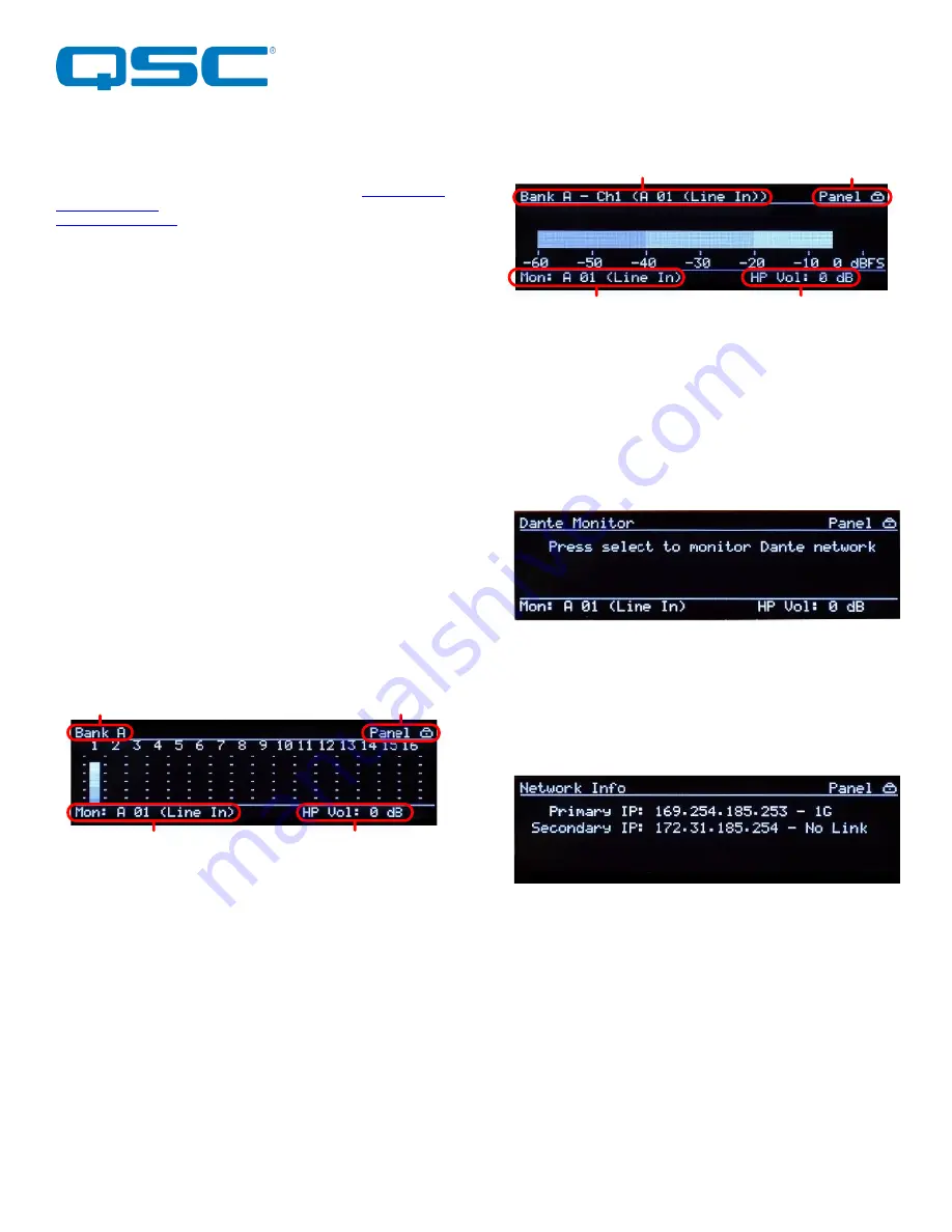
3.1.1 – Bank Metering Views 

There are two views  for bank  metering.  The  main part of each 
bank view shows meters for each analog input in that bank. This 
view can be used to select the monitor output if the panel lock is 
not active by pressing in the “Menu Nav” button. This activates a 
cursor that can be scrolled  used the knob to select one of the 
visible channels. Once the desired channel is selected, press the 
separate “Monitor Select” button and that channel  will  when  be 
routed to the headphone output. 
 

3.1.2 – Channel Metering Views 

 
Each individual input channel has its own view. The meter itself is 
shown in the horizontally across the main part of the view from 
left to right. The name of the current channels meter being shown 
is  displayed  in  the  upper  left  hand  corner.  The  name  in 
parenthesis that follows the name is the channel name that this 
channels is identified by on the Dante network. This view can also 
be used to select the monitor output if the front panel lock is not 
active.  To  do  so,  with  the  desired  channel  on  view,  click  the 
“Monitor Select” button. 
 

3.1.3 – Dante Monitor View 


As well as  monitoring the  local input channels, the  headphone 
output can also be used to monitor channels from the network. 
This view can be used to select Dante channels as a source for 
the headphone output if the front panel lock is not active. When 
selected, any Dante audio routed to the Dante receive channels 
will be heard through the headphone output. 
 

3.1.4– Network Info View 

 
The Network info view shows the IP addresses and link speed of 
the D32i’s interfaces. In redundant mode, both a primary and a 
secondary interface will be shown.  The primary port speed will 
always indicate the faster of the two possible primary links if they 
are both used. The same is true the secondary port speed if both 
secondary links are used. 
 
In switched mode, only one interface with its IP address is shown 
and the speed indicated will be the fastest speed of any of the 
four possible links. 
 

Panel Lock

Headphone Volume

Headphone Channel

Screen name

Channel Name (Dante Tx Name)

Headphone Channel

Headphone Volume

Panel Lock

Содержание Atterotech Synapse D32i

Страница 1: ... QSC and the QSC logo are registered trademarks of QSC LLC in the U S Patent and Trademark office and other countries All other trademarks are the property of their respective owners Patents may apply or be pending www qsc com 614 0003939 Synapse D32i Dante AES67 Network Audio Interface 32 Line Level Analog Inputs User Manual ...

Страница 2: ...ticularly at plugs convenience receptacles and the point where they exit from the apparatus 11 Only use attachments accessories specified by Attero Tech 12 Use only with the cart stand tripod bracket or table specified by the manufacturer or sold with the apparatus 13 When a cart is used use caution when moving the cart apparatus combination to avoid injury from tip over 14 Unplug this apparatus d...

Страница 3: ...uency energy and if not installed and used in accordance with the instruction manual may cause harmful interference to radio communications Operation of this equipment in a residential area is likely to cause harmful interference in which case the user will be required to correct the interference at their own expense This symbol means the product must not be discarded as household waste and should...

Страница 4: ...a Redundant Network 8 2 4 3 Using on Standalone Network 9 3 Device Operation 10 3 1 Display View Operation 10 3 1 1 Bank Metering Views 10 3 1 2 Channel Metering Views 10 3 1 3 Dante Monitor View 10 3 1 4 Network Info View 10 3 1 5 Dante Info View 11 3 1 6 Version View 11 3 1 7 No Network 11 3 1 8 Identify 11 3 2 Headphone monitoring 11 3 2 1 Headphone Volume 11 3 2 2 Headphone Mute 11 3 3 Factory...

Страница 5: ...tailed feedback for audio confidence monitoring and diagnostics The 24V power supply comes pre mounted to the D32i chassis but there is also support for a secondary external 24V DC supply for optional power redundancy On the network side there is a fully redundant Dante interface utilizing both RJ45 connectors and SFP ports The SFP ports allow the D32i to utilize direct fiber connectivity for long...

Страница 6: ... Panel FRONT PANEL 1 Headphone Jack 2 Headphone Mute Indicator 3 Headphone Volume Mute Knob 4 Factory Reset Switch 5 OLED Display 6 Front Panel Nav Knob 7 Monitor Select Switch 8 Device Power Status LED DEVICE FEATURES REAR PANEL 9 Bank A Input 1 16 10 Bank B Inputs 17 32 11 SFP port Primary 12 SFP Secondary 9 Bank A Input 1 16 10 Bank B Inputs 17 32 11 SFP port Primary 12 SFP Secondary 13 Etherne...

Страница 7: ... Wiring All connections to the Synapse D32i should be made before the power is applied Attach audio sources that will be used to the analog audio inputs The analog audio inputs are balanced so be sure to check what output type the source to be connected uses in order to find how to connect it correctly 2 2 1 Unbalanced Output to an Balanced Input Balanced Input Terminal Block Plug 2 Wire Cable Sle...

Страница 8: ...uct manufacturer as well 2 4 2 Using on a Redundant Network The D32i is setup for use in a redundant network out of the box In this mode the D32i effectively has two separate network connections each with its own unique IP address Both IP addresses also need to be on completely different subnets By default both ports of the D32i in redundant mode will get their own IP from a DHCP server if one is ...

Страница 9: ...y ports having completely different IP addresses Therefore this should be avoided Figure 5 Standalone connection in Redundant mode For full flexibility in a standalone network the D32i should be reconfigured to Switched mode This is easily done by connecting one of the primary ports to the standalone Dante network and then using Dante controller to switch the mode Figure 6 Standalone connection in...

Страница 10: ...output if the panel lock is not active by pressing in the Menu Nav button This activates a cursor that can be scrolled used the knob to select one of the visible channels Once the desired channel is selected press the separate Monitor Select button and that channel will when be routed to the headphone output 3 1 2 Channel Metering Views Each individual input channel has its own view The meter itse...

Страница 11: ...splay on any of the metering views The volume is controlled with the monitor volume knob just to the right of the output jack itself Turning the knob clockwise increases volume while turning it counter clockwise decreases the volume level 3 2 2 Headphone Mute The headphone volume knob also acts as a mute control The state of the mute is indicated by the mute LED just to the left of the volume knob...

Страница 12: ...front panel mounted headphone jack for monitoring The Dante interface shall support a switched or redundant network mode The device shall support AES67 audio network interoperability The device shall have two integrated Gigabit Ethernet ports on RJ 45 connectors and 2 gigabit SFP expansion slots for connectivity to a Dante network All parameter changes will be non volatile and self restoring in th...

Страница 13: ... pin line level Terminal Block option 4 TASCAM pinout compatible DB25 balanced analog DB 25 Input Impedance 10 kΩ Pad Inactive 50 kΩ Pad Active Maximum Input Levels 24 dBu 0 5 dB Pad Inactive 10 dBV 0 5 dB Pad Active THD N 0 005 Dynamic Range 105 dB Frequency Response 20 20kHz 0 5dB Headphone Output Output Type Stereo headphone on TRS Maximum output level 15mW into 32 Ohms THD N 0 01 15mW Dante Ne...

Отзывы: