background image

4

WARRANTY

_____________________________________

The HF-2000 is warranted against defects in material and workmanship for a period
of two years for the original date of sale. This warranty does not cover the 3-500
triode which carries a separate warranty issued buy its manufacturer. Please check
the warranty card which comes with the tube.


During the warranty period, QRO

Technologies, Inc. will repair or  replace the amplifier at our option if it is defective in
any way in material and workmanship. The warranty does not cover any defects
resulting from improper use by the buyer or inadequate maintenance. In such cases
the repair will be billed at prevailing  service rates.

For warranty service or repair, the amplifier must be returned to the factory for
authorized service. The buyer shall prepay shipping and insurance charges, QRO
Technologies, Inc. will pay shipping and insurance charges to return the amplifier to
the buyer. Please call the factory at 1-800-956-2721 for shipping instructions. Make
sure when returning the amplifier you have insured the instrument for the full
replacement cost. QRO Technologies, Inc. is not liable for any damage incurred
during return shipments.

PROPRIETARY NOTICE

_____________________________________ 

This instruction manual, schematic diagrams, and technical data herein disclosed,
are proprietary to QRO Technologies, Inc. and shall not, without express written
permission of QRO Technologies, Inc.. be used, in whole or part to solicit quotations
from a competitive source or used for manufacturing by anyone other than QRO
Technologies, Inc. The information herein has been developed at private expense,
and may only be used for operation and maintenance reference purposes or for
purposes of engineering evaluation and incorporation into technical specifications
and other documents which specify procurement of products from QRO
Technologies, Inc. This amplifier is covered by copyrights both in the United States
of America and throughout the world. 

Содержание HF-2000

Страница 1: ...7 West High Street P O Box 939 Bryan OH 43506 USA Tel Fax 419 636 2721 E Mail sales qrotec com Internet http www qrotec com PUBLICATION DATE JUNE 1995 COPYRIGHT 1995 BY QRO TECHNOLOGIES INC ALL RIGHTS...

Страница 2: ...50 ohms unbalanced with SWR 2 1 or less Tube Requirement 2 3 500Z 3 500ZG 3 500C Power Line Requirement 120 VAC 50 60 Hz at 20 amperes maximum 240 VAC 50 60 Hz at 10 amperes maximum Front Panel Multi...

Страница 3: ...ower Line Considerations 8 9 Antenna 9 Grounding 9 Equipment Interconnections 10 Safety Interlock Switch 10 Driving Power 10 Tube 11 Reading the Meters 11 Tune Up Procedure 11 12 Using the ALC Adjust...

Страница 4: ...to return the amplifier to the buyer Please call the factory at 1 800 956 2721 for shipping instructions Make sure when returning the amplifier you have insured the instrument for the full replacement...

Страница 5: ...neutral earth pole of the power supply Before operating this unit ensure that the protection conductor green wire is connected to the ground earth protective conductor of the power outlet Do not defe...

Страница 6: ...the amplifier so the front panel is facing you Position the transformer so the primary leads are on your left and the secondary leads are on your right The amplifier s transformer compartment should b...

Страница 7: ...is connected to terminals 2 4 If there is a white wire connected to left side of terminal 6 remove it an connect it to left side of terminal 5 Also if there is a black wire connected to the left side...

Страница 8: ...g fan Do not place any books magazines manuals or equipment that will impede the free flow of air near the sides andthe hot air exhaust holes located on the top of the cabinet The internal fan allows...

Страница 9: ...urrent AC or DC on the same premises shall be of such circuits are not interchangeable When you install a new plug make sure it is connected according to your local electrical code Keep in mind that t...

Страница 10: ...will have to use some other means For instance you could use a shorted RCA phono plug by placing it in the Key XMT socket Then you would have to manually turn off and on the Operate Standby switch lo...

Страница 11: ...es without drive applied so the fan will cool the tubes before you turn the Amplifier off READING THE METERS Refer to Front Panel Pictorial while you read the following information Multimeter The Mult...

Страница 12: ...ne Voltage Freq Mhz Band Drive Tune Control Load Control Plate Voltage Plate Current Grid Current Power Output 1 80 160 1 90 160 3 55 80 3 90 80 7 20 40 14 20 20 18 10 17 21 30 15 24 90 12 28 50 10 28...

Страница 13: ...iately reduce the drive 9 Again key your transceiver and observe the peak RF watts on your wattmeter Adjust the Tune Control and Load Control for maximum output on your wattmeter This is accomplished...

Страница 14: ...ur initial operation you may want to check the tuned input circuits for each band to see if it has the proper match A nominal match will show no more than 10 watts reflected with 100 watts of drive ap...

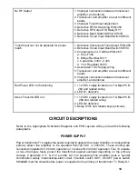
Страница 15: ...ms PCB and the Schematic Diagrams to locate and identify the parts listed in this chart If a particular part is mentioned as a possible cause check that part and other components connected to it to se...

Страница 16: ...h SW401A B Meter Switch PCB 510 5 M 2 Multimeter Plate idle current over 160 ma or does not read zero in standby mode 1 Components on LV Bias PCB 260 a Transistor Q302 b Diodes D303 D310 c Resistor R3...

Страница 17: ...PL1 PL4 Meter Switch PCB 510 No Grid Current Meter Indication with Plate Current Indication OK 1 Components on LV Bias PCB 260 a Resistor R311 b Capacitor C306 2 Grid Meter M 1 Amplifier will not key...

Страница 18: ...ed on LV Bias PCB 260 and related wiring 2 LED D1 defective Green Transmit LED not 1 12 VDC supply located on LV Bias PCB 260 and related wiring 2 LED D2 defective 3 Relay K301 and related keying circ...

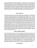
Страница 19: ...positive diodes D101 D105 conduct and capacitors C201 C204 are charged During the other half of the AC line cycle the red lead connected to the junction of D105 D106 becomes positive Capacitors C205 C...

Страница 20: ...e plate lead to suppress any VHF parasitic oscillations The positive side of the power supply B is connected to the tube s plate through RFC3 Plate Choke Capacitor C56 provides a low impedance path to...

Страница 21: ...R302 R304 form a series multiplier resistance for meter M 2 while resistor R301 forms a current shunt for the meter Diodes D311 D312 plus capacitor C307 provide M 1 with transient protection IP PLATE...

Страница 22: ...01 and resistors R601 R602 plus diode D602 form a break make delay circuit for RY1 RY2 This helps to make the proper latching and unlatching sequence for relays K301 RY1 and RY2 Transistor Q601 plus a...

Отзывы: