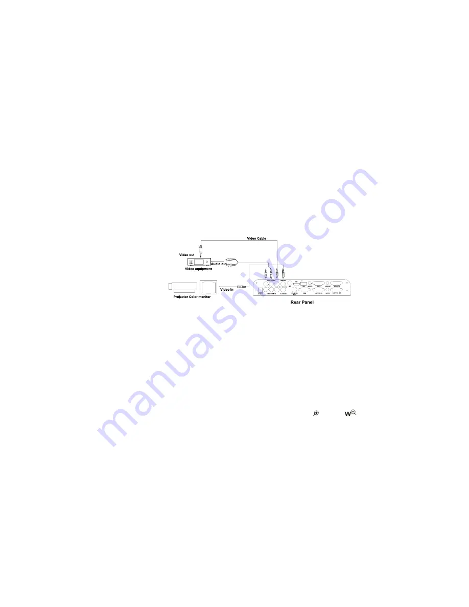
In the step 2, the connection between the S-video and C-Video output signals
to the projector was established, where the RGB cable runs from the
visuali
V
er and goes to the projector. Once the connections have been made
as detailed in the steps 2, 3, 4, input signals from the computer
、
visuali
V
er
CCD, C-Video and S-Video are going to the RGB1 input on the projector and
will be displayed on the projector screen as RGB1. These signals can be seen
in turn when pressing “CCD/PC1/PC2” and “S-VIDEO/VIDEO” on the control
panel of the visuali
s
er.
Step 5: Connect to the second video equipment with video input.
4. Turn on the power by pressing the “POWER” button.
PAL/NTSC VIDEO OUTPUTS
The S-Video and composite video outputs are set to PAL (NTSC) during
manufacturing.
WORKING ON THE STAGE
1. Place your material on the platform.
2. Select the enlargement required using the “
T
” and “
” buttons.
3. Adjust the focus using the “Near” and “Far” buttons or “AUTO” button.
LIGHT
The arm lights are powered on when the power is turned on. Each time you
press the “LAMP” buttons, the lighting changes occur as demonstrated.
8


