QJE 3003X Скачать руководство пользователя страница 9

2-2. INSTALLATION AND HANDLING PRECAUTIONS

      When placing the Power Supply in service at your workplace, observe

the following precautions for best instrument performance and longest

service life.

1.   Avoid placing this instrument in an extremely hot or cold place.

          Specifically, don’t leave this instrument in a closed car, exposed

to sunlight in midsummer, or next to a space heater.

2   Don’t use this instrument immediately after bringing it in from the

cold.

        Allow time for it to warm to room temperature. Similarly don’t move

it  from  a  warm  place  to  a  very  cold  place,  as  condensation  might

impair its operation.

3. Do not expose the instrument to wet or dust environments.

4. Do not place liquid-filled containers (such as coffee cups) on top

of this instrument.

A spill could seriously damage the instrument.

5. Do not use this instrument where it is subject to serve vibration,

or strong blows.

6.  Do  not  place  heavy  objects  on  the  case,  or  otherwise  block  the

ventilation holes.

7.  Do  not  use  this  Power  Supply  in  strong  magnetic  fields,  such  as

near motors.

8. Do not insert wires, tools, etc, through the ventilation holes.

9. Do not leave a hot soldering iron near the instrument.

10. Do not place this instrument face down on the ground, or damage

to the knobs may result.

11 .Do not connect other power source to +.- of the output terminal.

6

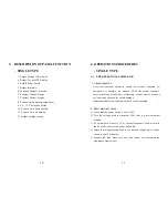
10.   DESCRIPTION OF PANEL FUNCTION

– DUAL TYPE

1. Constant Voltage Display – Ch.1

2. Output Voltage Display – Ch.1

3. Constant Current Display – Ch.1

4. Output Current Display – Ch.1

5. Current Limit Adjustment Indicator – Ch.1

6. Current Limit Up Setting – Ch.1

7 .Current Limit Down Setting – Ch.1

8. C.V. / C.C. Selection Switch – Ch.1

9. Output Voltage Setting – Ch.1

10. Output Terminal – Ch.1

11. Extended Output terminals – Ch.1

12. Serial Function Select Switch

13. Serial Function Indicator

14. PARALLEL Function Indicator

15. PARALLEL Function Select Switch

16. Constant Voltage LCD Display – Ch.2

17. Output Voltage LCD Display – Ch.2

18. Constant Current Display – Ch.2

19. Output Current Display – Ch.2

20. Current Limit Adjustment Indicator – Ch.2

21. C.V. / C.C. Selection Switch – Ch.2

15

Содержание 3003X

Страница 1: ...REGULATED DC POWER SUPPLY 3003X 3005X 5003X 3003X 3005X 3003X INSTRUCTION MANUAL...

Страница 2: ...sion terminal connection please refer to Fig 8 4 When the unit is used with the high frequency instruments like ultrasonic soldering tool the electric power supply should be grounded Fig 8 22 CONTENTS...

Страница 3: ...current when the unit is used in such a place where ventilation is interrupted or a radiation exists from other equipments 2 Use the instrument within 10 tolerance of the specified voltage from the p...

Страница 4: ...of output terminals when operating in other mode Fig 7 20 SAFETY SUMMARY SAFETY PRECAUTIONS Please take a moment to review these safety precautions They are provided for your protection and to preven...

Страница 5: ...ALLEL function operating method 1 Turn on the power by pressing the POWER switch 2 Under normal condition to adjust both voltage knob to obtain same or similar voltage value 3 Push the PARALLEL button...

Страница 6: ...s dual power supply will work independently Notice When operating at constant current condition the constant current value should be set at the same value Fig 5 18 WARRANTY Warranty service covers one...

Страница 7: ...10 Continuously working under full loaded condition 4 9 OPERATION PROCEDURES DUAL TYPE 9 1 Constant Voltage Setting Method 1 Turn on power switch 2 Adjust voltage setting knob to the desired voltage...

Страница 8: ...nals Ch 2 5 Extended Output Terminals Ch 2 6 Output Terminals for 5V 3A 7 Power Switch 16 2 PRECAUTIONS 2 1 EXCHANGE METHOD OF FUSE If you wish to change FUSE F1 please use driver and pull it over as...

Страница 9: ...erwise block the ventilation holes 7 Do not use this Power Supply in strong magnetic fields such as near motors 8 Do not insert wires tools etc through the ventilation holes 9 Do not leave a hot solde...

Страница 10: ...th a soft cloth dipping a neutral detergent 2 If the surface of the panel is dirty use the same method to clean If the panel is heavily stained rub the affected area lightly with a soft cloth soaked i...

Страница 11: ...2 0 30V 2 5V CURRENT STEPWISE 30mA 3mA 50mA 5mA 30mA 3mA 30mA 3mA 50mA 5mA 50mA 3mA OUTPUT CURRENT 0 3A 0 5A 0 3A 0 3A 2 0 5A 2 0 5A 2 3A LINE REGULATION CV 0 02 2mV CC 0 05 5mA LOAD REGULATION CV 0...

Страница 12: ...rminal 4 Push the UP or DOWN button to obtain the desired current value 5 When pushing and hold the UP or DOWN button over 0 8 sec the value will go up or go down continuously 6 Release the shortend w...

Страница 13: ...s should be visually inspected for damages For example the chassis VR knobs output terminals Function buttons fuse holders voltmeters current meters switches etc should be checked for visible damage I...

Отзывы: