3
Operation Manual of Intelligent High Speed Dome Camera
Chapter Two Wiring and Setup of Dome System
I. Wiring of Dome System
1
.
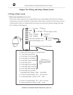
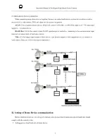
Basic system connection
(One dome device)
From the basic system connection, user can understand the electric wiring attribute of the dome device and bring
great operation convenience of installation, testing and demo. When using this product for the first time, please read
carefully and follow this electric wiring drawing as any wrong wiring may lead to permanent damage of the dome
device or damage of other equipment.
!Attention: No operation when the dome device is power on.
Yellow-Green Interphase Color
Yellow-Green Interphase Color
Orange )
Yellow RS485B(-)
BNC Video Output
RedBl
ack
Description about Connections for Alarming Function
:
No.1 Alarm Input: Red and White
No.2 Alarm Input: Yellow and White
No.3 Alarm Input: Grey and White
No.4 Alarm Input: Orange and White
No.5 Alarm Input: Brown
No.6 Alarm Input: Green and White
No.7 Alarm Input: Brown and White
No.8 Alarm Input: Bule and White
No.8 Alarm Input: Gray and White
Alarm Intput Public Terminal
(
COM1
)
: Black/White
No.1 Alarm Constant ON Output
(
NO1
)
: Blue and Green
No.1 Alarm Output Public Terminal
(
COM1
)
: Blue
No.2 Alarm Constant ON Output
(
NC2
)
: Brown and Green
No.2 Alarm Output Public Terminal
(
COM2
)
: Green
The brown wire
stranded with alarm input
wire is the alarm system
ground
Connected to
Ground
Controller of
the Dome
Power Supply of Dome
Display
External Connection for Alarm Input/Output
AC24V Input
Содержание PTZ
Страница 1: ...3 Intelligent High Speed Dome...
Страница 12: ...8 Operation Manual of Intelligent High Speed Dome Camera...
Страница 44: ...40 Operation Manual of Intelligent High Speed Dome Camera...


