Appendix
XT4500
30
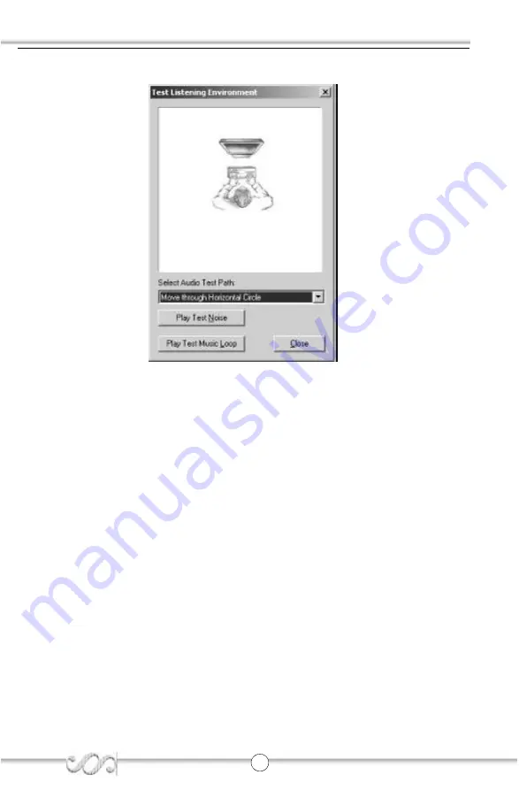
5. Select test noise or music loop.
Страница 1: ...l damages arising out of the use or the possibility of such damages All trademarks are the property of their respec tive owners If you need any further information please visit our web site www qdigrp com This item checklist is only available for retail market Completely check your package If you discover damaged or missing items contact your retailer Item Checklist XT4500 series mainboard QDIUtil...
Страница 2: ...00 Electromagnetic compatibility EMC Part 3 Limits Section 2 Limits for harmonic current emissions equipment input current 16A per phase þ EN 61000 3 3 A1 2001 Electromagnetic compatibility EMC Part 3 Limits Section 3 Limits of voltage fluctuations and flicker in low voltage supply systems for equipment with rated current 16A þ EN 55024 A1 2001 Information technology equipment Immunity charac teri...
Страница 3: ...t Mainboard Manufacturer QDI TECHNOLOGY HK Inc Address 23Floor Lincoln House Taikoo Place 979 King s Road Quarry Bay HONG KONG Supplementary Information This device complies with Part 15 of the FCC Rules Operation is subject to the following two conditions 1 this device may not cause harmful interfer ence and 2 this device must accept any interference received including interference that may cause...
Страница 4: ...nd MIDI Joystick Connnector 6 6 Channel Audio 6 ATX 12V Power Supply Connectors Power Switch 7 HardDisk LEDConnector HD_LED 7 Reset Switch RESET 7 PowerLEDConnector PWR_LED 8 FanConnectors CPU_FAN PWR_FAN 8 USB3 USB4Connectors 9 AudioConnectors CD_IN 9 AudioInterface F_AUDIO 10 SPEAKER Connector 10 JumperSettings 11 ClearCMOS CLR_CMOS 11 Chapter 3 BIOS Description 12 AWDFLASH EXE 13 AWARD BIOS Des...
Страница 5: ...sure to unplug the AC power supply before adding or removing expansion cards RAM or other system peripherals otherwise your mainboard and RAM might be seriouslydamaged Note This manual is suitable for XT4500 series of mainboards Each mainboard is carefully designed for the PC user who wants different features 6A with 6 channel Audio L with onboard LAN ...
Страница 6: ...formance and cost effective mATX platform The new integrated technologies together with AC 97 audio AGP 4X 4 USB 2 0 ports and ATA100 66 33 give customers an advanced multi mediasolutionat reasonableprice It provides 400 533MHzhostbus speed to support new Intel prescott Pentium 4 and Celeron socket 478 proces sors and the DDR266 333 memory ...
Страница 7: ...AN optional 10 100 Mbit sec Ethernet support 10 100M LAN interface built in on board USB 2 0 USB 2 0 compliant operates at 480Mbps about 40X times faster than USB 1 1 which currently works at a snails pace of just 12Mbps Provides 4 USB 2 0 ports Onboard I O One floppy port supporting up to one 3 5 or 5 25 floppy drives with 360K 720K 1 2M 1 44M 2 88Mformat One high speed 16550 compatible COM with ...
Страница 8: ...ced Configuration and Power Interface and ODPM OS Directed Power Management Supports ACPI power status S0 full on S1 power on suspend S4 suspend to Disk depends on OS and S5 soft off Main Expansion Slots and Connectors Slot Port Quantity Description PCI 2 PCIslots IDE 2 IDEports FLOPPY 1 Floppy Drive port DDR 2 DIMMsocket USB 4 USB connectors LAN 1 optional LAN connector COM 1 COMconnector PARALLE...
Страница 9: ...t chart for locations of all jumpers external connectors slots and I O ports Furthermore this section lists all necessary connector pin assignments for your reference The par ticular state of the jumpers connectors and ports are illustrated in the following figures Before setting the jumpers or inserting these connectors please pay attention to the direction ...
Страница 10: ... Serial Port Connector COM1 optional The parallel port connector can be connected toa parallel devicesuch as a printer The serial port COM1connector can be connected to a serial port device such as a serial port mouse You can enable disable them and choose the IRQ or I O address in Integrated Peripherals fromAWARDBIOSSETUP Be sure to unplug the AC power supply before adding or removing expansion c...
Страница 11: ...dio which consists of Front Left Front Right Rear Left Rear Right Center and Woofer for a complete surround sound effect When 6 Channel audio is available the front Left Right jack can be connected to the Front speskers the Back Left Right jack can be connected to the rear speakers and the Center Woofer jack can be connected to the center speaker and woofer Microphone function is offered by F_AUDI...
Страница 12: ...wering up your system first turn on the mechanical switch of the power supply if one is provided then push once the power switch When powering off the system you needn t turn off the mechanical switch just push once the power switch XT4500 series mainboard only support ATX12V power If you change Soft off by PWR BTTN from default Instant off to Delay 4 Sec in the POWER MANAGEMENT SETUP section of t...
Страница 13: ...tatus the LED is off The connector has an orientation Fan Connectors CPU_FAN PWR_FAN The fan speed of these fans can be detected and viewed in PC Health section of the CMOSSETUP HDD LED POWER LED Power S W RESET R e s e r v e d POWER LED HDD LED HDD LED HDD LED G N D P O W E R EMPT Y REVERSE G N D P O W E R PWR LED RESET PWR LED POWER SW PWR_FAN CPU_FAN 12V SENSE GND 12V GND SENSE ...
Страница 14: ...headers on board which may connect to front panel USB cable optional to provide addi tional two USB ports Audio Connector CD_IN CD_IN is Sony standard CD audio connector it can be connected to a CD ROM drive through a CD audio cable CD_IN CD Right Channel Common CD Left Channel FUSB3_4 1 5V USB0 USB0 GND CUT GND USB1 USB1 5V GND ...
Страница 15: ...ailable the RearAudio in case speakers will be cut off An onboard amplifier is provided for the earphone When the FrontAudio is absent Pin5 and Pin6 Pin9 and Pin10 must be short connected SPEAKER Connector SPK_DATA GND NC SPK_VCC 1 F_AUDIO Audio Interface Pin No Symbol Pin No Symbol 1 AUD_MIC 2 AUD_GND 3 AUD_MIC_BIAS 4 AUD_VCC 5 AUD_FPOUT_R 6 AUD_RET_R 7 NC 8 Cut away 9 AUD_FPOUT_L 10 AUD_RET_L 2 ...
Страница 16: ...pin1 pin2 1 2 closed and to represent pin2 pin3 2 3 closed Jumper Symbol Description Represent 1 2 set pin1 and pin2 closed 2 3 set pin2 and pin3 closed close set the pins closed open set the pins opened Clear CMOS CLR_CMOS If you want to clear CMOS unplug the AC power supply first close CLR_CMOS pin1 pin2 once set CLR_CMOS back to the normal status with pin2 pin3 connected then power on the syste...
Страница 17: ...s AWARD BIOS Setup program that provides a Setup utility for users to modify the basic system configuration The information is stored in CMOS RAM so it retains the Setup information when the power is turned off This chapter provides you with the overview of the BIOS Setup ...
Страница 18: ...oad the updated BIOS file from the Website http www qdigrp com Please be sure to download the suitable BIOS file for your mainboard 4 Decompress the file download copy the BIOS file xx bin to the bootable diskette and note the checksum of this BIOS which is located in readme file 5 Reboot the system from the bootable diskette created 6 Then run the AWDFLASH utility at the A prompt as shown below A...
Страница 19: ...e desired in each item QDI Innovation Features This section describes QDI innovation EASY technology Advanced BIOS Features This section allows you to configure your system for basic operation You have the opportunity to select the system s default speed boot up sequence keyboard operation shadowing and security Advanced Chipset Features The chipset features setup is used to change the values of t...
Страница 20: ...eing disabled Once the password is disabled the system will boot and you can enter BIOS Setup freely PASSWORD DISABLED If you have selected System in Security Option of BIOS Features Setup menu you will be prompted for the password every time the system reboots or any time you try to enter BIOSSetup If you have selected Setup at Security Option from BIOS Features Setup menu you will be prompted fo...
Страница 21: ... order and you need to restart your computer until all the drivers are installed A Chipset software B IAA Setup C USB2 0Driver D Audio Driver E Network Driver optional F DirectX 2 Browse CD You could read all the contents contained in this CD including Utility and Documents The files included in Utility are A Awdflash exe B Cblogo exe C Lf exe The files included in Documents are A Adobe Acrobat Re...
Страница 22: ...iviert werden Falls Fehler im Flash ROM den Bootvorgang behindern versucht das System drei Mal den Rechner hochzufahren bei Misserfolg schaltet es auf die althergebrachte Art zu booten um das heißt es dauert wieder ebenso lang wie frü her Anschließend kann die BootEasy Technik wieder aktiviert werden QDI BootEasy German TheBIOS of the mainboard is contained inside the Flash ROM Severeviruses sucha...
Страница 23: ...nserte el procesador en el socket y conecte el ventilador del procesador en el conector de su placa base QDI XT4500 marcado como CPUFAN 6 Insertelosmó dulosdememoriaenlosbancos dememoriaDIMMdesuplacabaseQDI XT4500 7 Insertelas tarjetas PCI y o la tarjeta AGP en las bahí as deexpansió nde suplaca base QDIXT4500 8 Conecte los perifé ricos internos IDE y las disqueteras mediante los cables de datos e...
Страница 24: ...ia de inicio correcta para que el sistema operativo pueda iniciarse 5 Despué s de la instalació n del sistema operativo asegú rese que no hay conflictos con ningú n dispositivo de su sistema 6 Entonces despué s del ú ltimo paso proceda a la instalació n de los controladores de los diferentes dispositivos Un disco compacto con controladores de QDI esta incluido en el paquete de la placa base QDI XT...
Страница 25: ...ies avec cette derniè re lors de son achat 4 S assurer que la carte mè re de la sé rie QDI XT4500 est maté riellement correctement configuré e pour cela vé rifier que les cavaliers insé ré s sur les broches inté gré es de cette derniè re sont correctement positionné s Dans ce but il est important de se ré fé rer àla section nommé e Configuration des cavaliers du chapitre numé ro 2 nommé Instructio...
Страница 26: ...ation du système 1 Dé marrer le systè me en pressant l interrupteur de fonctionnement de l unitécentrale del ordinateur 2 Presser la touche Suppr du clavier afin d entrer dans le menu de BIOS 3 Dans le menu de BIOS nommé QDI Innovation features ajuster la fré quence de fonctionnement du processeur Attention il est fortement recommandéde charger les ré glages de sû retépar dé faut afin d é viter un...
Страница 27: ...llerlespilotesenrespectantl ordrepré dé finitetderedé marrer le systè me aprè s avoir effectuél installation de tous les pilotes Applications contenues dans le dossier A Chipset software B IAA Setup C USB2 0Driver D Audio Driver E Network Driver optional F DirecrX 2 Browse CD Avec cette option il est possible de consulter l ensemble des donné es contenues surleCD ROMd installationQDI Applications ...
Страница 28: ...sa sul cavo deve essere inserita nellapposito connettore in corispondezza del pin 1 9 Conettere la mainboard con il cavo di alimentazione proveniente dall alimentatore il connettore dell interuttore di stand by il conettore del led di segnalazione acceso il connettore led di funzionalita HARD DISK il connettore dello spekear interno al CASE consultareil manualecapitolo2 EXTERNALCONNECTORS Dopo chi...
Страница 29: ... dellaVs mainboard inmodofacileeveloce Dovreste installare i driver nella seguente succesione finito cio bisogna far ripartire il personal computer A Chipset software B IAA Setup C USB2 0 Driver D Audio Driver E Network Driver optional F DirecrX 2 Guardando il CD Questomanualediinstallazionee disponibileanchenellasuaversione elettronicaall interno del cd accompagnativo insieme anche diverse utili ...
Страница 30: ... Function You can start to use the 4 6 channel audio function After the driver is installed completely The first you can connect 4 or 6 speakers to the audio output connector Then open utility to set the work parameter Attaching speakers To perform multichannel audio operation connect multiple speakers to the system You should connect the same number of speakers as the audio channels you will sele...
Страница 31: ... 26 6 Channel Analog Audio Output Description Both Line In and MIC are converted to Line Out function under 6 channel configuration Line Out Front channels Line Out Rear channels Line Out Center and Subwoofer channels ...
Страница 32: ...tray at the bottom of the screen 2 Select the multi channel operation you prefer from Speaker Setup Layout under the Listening Environment tab and Click OK 3 Select any surround sound effect you prefer from the Environment Models pull down menu Clickhere Click here and the pull down menu will appear ...
Страница 33: ...er work properly If any speaker fails to sound then check whether the cable is inserted firmly to the connector or replace the bad speakers with good ones Testing Each Speaker 1 Double click the audio icon from the window tray at the bottom of the screen 2 Click the Listening Environment tab 4 Click the MIDI Music Synthesizer tab and set synthersizer default sound Clickhere ...
Страница 34: ...T4500 29 3 The following window appears and click Test button 4 The following window appears and Select Audio test path from the Audio Test Path pull down menu Clickhere Clickhereandthepull down menu will ap pear ...
Страница 35: ...Appendix XT4500 30 5 Select test noise or music loop ...
Страница 36: ...thelever pivot The CPU will only fit in the correct orientation If the CPU is correctly installed the pins should be completely embedded into the socket and can not be seen 3 Hold the CPU down firmly and then close the lever to complete installation Warning Overheating will seriously damage the CPU and system always make sure the cooling fan can work properly to protect the CPU from overheating ...
Страница 37: ...Board Layout of XT4500 Note The layout includes all options It is for your reference only ...
Страница 38: ...CLR_CMOS FDD Top PS 2 Mouse Bttm PS 2 Keyboard LPT COM1 PANEL Note pin1 for a jumpers are located on the side with black line 1 PWR_LED 2 PWR_SW EMPTY 3 HDD_LED 4 RESET REVERSE 1 2 3 4 FUSB3_4 F_AUDIO ATX 12V ATX_POWER North Bridge SPEAKER Top LAN Bttm USB0 1 Top LAN Bttm USB1 2 AUDIO ...