


PART 1 - PACKAGE CONTENTS
manuals and
softwa re
QS Serie s
QS408 • QS20 6
QS206 DVR
Pre-Installed
Hard Drive
Power Supply
for DVR
Remote Control
Manual and
Software CD
Ethernet
Cable
60-Foot
Power and Video Cable
(One per camera)
Grounding Cable
Not used in North America
Color Cameras with Stands
1 BNC(M) to RCA(M)
Adapter Cable
Power Supply and
4- or 8-Way Splitter
USB 2.0
Mouse
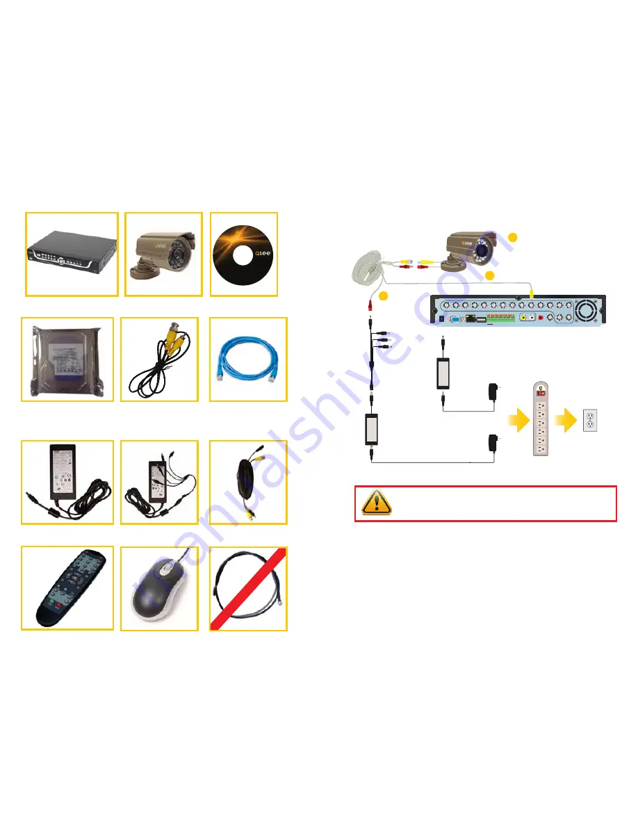
PART 2 - DVR CAMERA AND POWER CONNECTIONS
Revised 6/29/11
1 2
3
4
5
VGA
USB
AUDIO IN
CVBS OUT
AUDIO
OUT
VIDEO IN
1
GND
COM1
NO1
COM2
NO2
GND
485A-2
485B-2
GND
485A-1
485B-1
GND
+12V
GND
2
3
4
5
6
7
8
9
10
11
12
13
14
16
15
ALM IN
RJ45
DC +12V
IN
STEP 1: Connect the Cameras
to the Cables
Connect both camera leads to the matching
ends on the power/video cable.
Repeat for all cameras.
1A
Attach the BNC connector on the power/video cable to a
Video In port on the DVR. Repeat for all cameras.
1B
Connect the remaining
connector to one of the
ends on the power
splitter. Repeat for all
cameras.
STEP 2:
Connect the single end
of the power splitter to
the included power supply.
STEP 4:
Connect both power supplies to
a surge protector.
STEP 5:
Connect thesurge protector
to an outlet.
STEP 3:
Connect the other power supply to the DVR .
1C
IMPORTANT!
It is STRONGLY recommended to use a surge protector that
is UL-1449 rated. Look for a clamping voltage of 330 or lower, a Joule rating
of at least 400 and a response time of 10 nanoseconds or less.
The appearance of contents may differ from images shown.


