


8
9
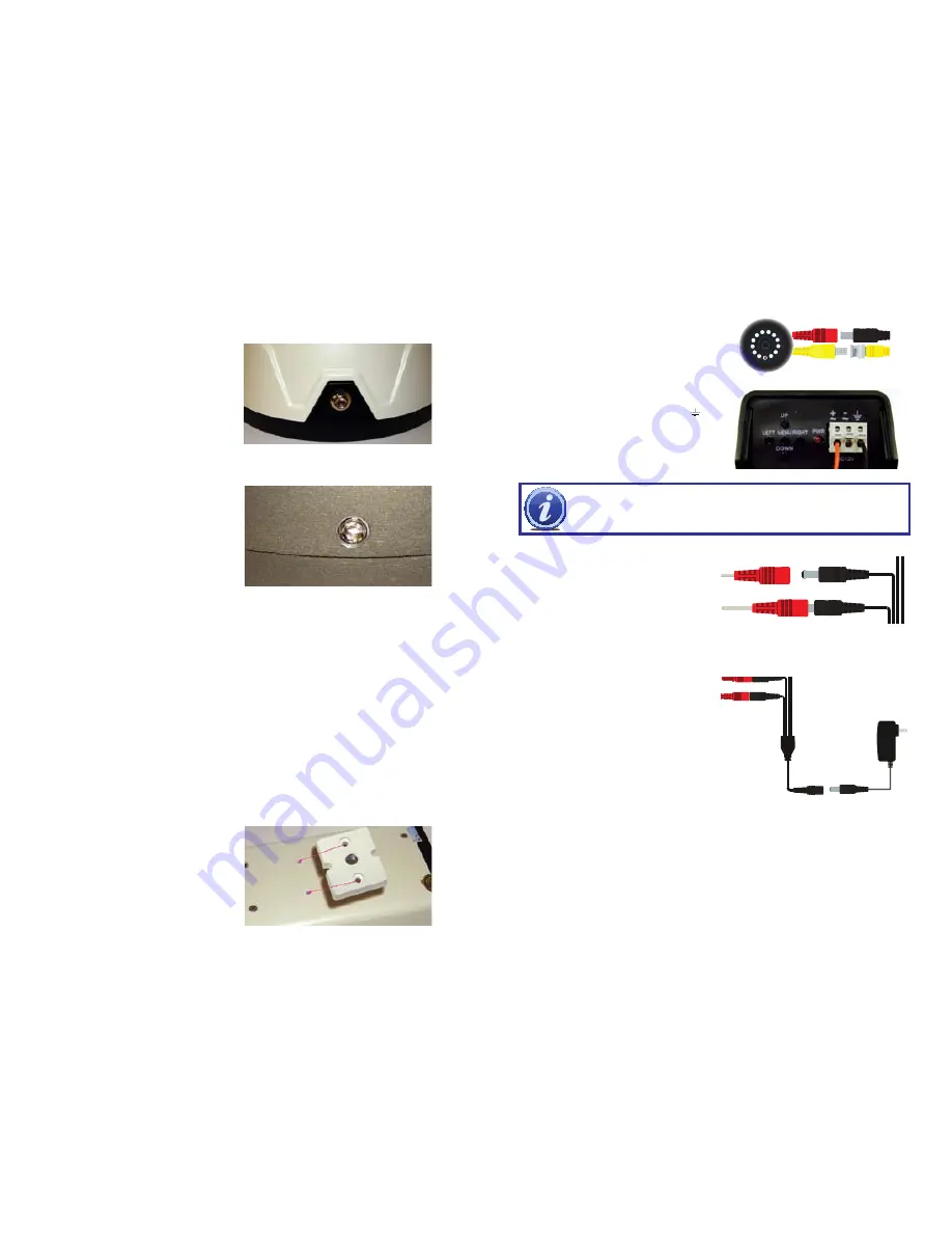
STEP 1.
Connect the BNC and power
leads from the camera to the matching
connectors on one end of the power
and video cable.
CONNECTING THE CAMERA TO A SECURITY DVR SYSTEM
DOME CAMERAS
(QD6001D, QD6002D and QD6003D)
STEP 1
. The mounting base on the dome cameras will need to be removed prior to
installing the camera. The method for removing the base varies by the model:
QD6001D
- Using the included hexagonal
wrench, unscrew the two bolts from the side
of the camera.
QD6001D Base
QD6003D Base
QD6503X Mounting Bracket
QD6002D
- The base of this camera unscrews from the rest of the body.
QD6003D
- Using the included hexagonal
wrench, unscrew the three hex screws
located around the sides of the camera.
STEP 2.
Once the base has been removed, position it where you want to mount the
camera and use it as a template to mark where to drill the holes for the included
mounting screws.
STEP 3.
Remove base and drill out holes
STEP 4.
Insert plastic expanders into holes
STEP 5.
Use included screws to mount base to surface.
STEP 6.
Attach camera to base.
BULLET CAMERAS
(QD6004B, QD6005B, QD6501B, QD6502B and QD6503X)
STEP 1
. At the desired location, use the included mounting template to drill the holes for
the mounting screws
STEP 2.
Insert the plastic expanders into the holes
STEP 3.
Mount the camera using the included screws.
QD6503X
This indoor camera requires a screw-type
mounting rod (available separately)
STEP 1.
Install the rod mount as directed.
STEP 2.
Attach the included mounting
bracket to the underside or top of the
camera as needed with the included
screws
STEP 3.
Attach camera to mounting rod.
CAMERA
IMPORTANT!
When connecting the power and video cable between the
camera and the DVR, the “male” power end (red plug in the illlustration)
connects to the matching power lead on the camera.
STEP 2.
For multi-camera packs
,
connect the power lead on the other
end of the cable to the plug from the
power splitter. Or, if your package
includes a power distribution panel,
connect the power lead to one of the
power jacks on the panel. Proceed to
Step 4
, below.
For single camera packages
,
connect the power lead to the power
adapter itself. In this case, you may
skip to
Step 4
.
STEP 3
. Connect the power lead on the
power splitter to the camera power
adapter.
DO NOT
plug the adapter
into an outlet at this time.
STEP 4
. Connect the BNC connector on the other end of the video/power cable to a
Video
In
port on the back of the DVR.
Repeat Steps 1 through 4 for all cameras before continuing.
STEP 5
. Plug the power adapter into a surge protector* or turn on the power panel.
*When selecting a surge protector, it is STRONGLY recommended to use one that is
UL-1449 rated, for a clamping voltage of 330 or lower, a Joule rating of at least 400
and a response time of 10 nanoseconds or less.
The
QD6503X
requires a special adapter
(included). The two bare wire ends must be
inserted into the Positive (+) and Ground ( )
ports on the power input box at the back of
the camera. The power cable plug connects
to the attached female power jack on this
adapter.


