6
A mode switch on the CLT-351R/L rear-panel is used to identify camera data format. The
CLT-351R/L receives Camera Link
TM
camera data and maps the pixels into the
corresponding parallel format per the 68-pin AIA digital interface standard. The CLT-
351R/L supports 8/10/12/14/16-bit single-channel, 8/10/12-bit dual-channel, and 8-bit
color Camera Link
TM
“base” configuration cameras. Four mode switch positions are used
to indicate camera data format. Switch settings are defined in Section 1.3.1.
Frame grabber timing signal characteristics are selected using the rear-panel mode switch.
One switch position is used to select the polarity of the line valid signal, and a second
switch position is used to select the polarity of the frame valid signal. In most cases, a
“high” state on the line enable and frame enable signals is used to envelope valid lines and
frames of video data, respectively. The settings enable the user to select either active-high
or active-low polarities for each timing signal. Note that the frame enable signal is not
used in line scan applications. Switch settings are defined in Section 1.3.1.
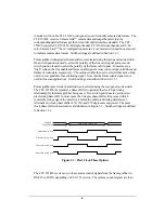
Frame grabber pixel clock characteristics are selected using the rear-panel mode switch.
The CLT-351R/L incorporates a phase shifter to optimize the clock /data timing
relationship for the frame grabber being used. Two switch positions are used to select
pixel clock phase shift. In most cases, the 0 degree phase shift setting is used which
centers the rising edge of the pixel clock within the valid pixel/timing data interval.
Alternatively, clock phase shifts of 90, 180, and 270 degrees are supported. The pixel
clock phase shifter characteristics are illustrated in Figure 1-3. Switch settings are defined
in Section 1.3.1.
Pixel Clock w/ 0
o
shift
Pixel Data &
Timing Signals
Valid Pixel & Timing Data
Pixel Clock w/ 90
o
shift
Pixel Clock w/ 180
o
shift
Pixel Clock w/ 270
o
shift
Figure 1-3: Pixel Clock Phase Options
The CLT-351R/L receives up-to four camera control signals from the frame grabber in
RS-422 or LVDS, depending on CLT-351 version. The camera control signals are then
Содержание CAMERA LINKT CLT-351L
Страница 21: ...19 Ground 68 N A tied to digital ground 1 Pixel Data MSB FG Frame Grabber ...
Страница 24: ...22 Ground 68 N A tied to digital ground 1 Pixel Data MSB FG Frame Grabber ...
Страница 27: ...25 Ground 68 N A tied to digital ground 1 Pixel Data MSB FG Frame Grabber ...
Страница 30: ...28 Ground 68 N A tied to digital ground 1 Pixel Data MSB FG Frame Grabber ...
Страница 33: ...31 Ground 68 N A tied to digital ground 1 Pixel Data MSB FG Frame Grabber ...
Страница 36: ...34 Ground 68 N A tied to digital ground 1 Pixel A MSB 2 Pixel B MSB FG Frame Grabber ...
Страница 39: ...37 Ground 68 N A tied to digital ground 1 Pixel A MSB 2 Pixel B MSB FG Frame Grabber ...
Страница 42: ...40 Ground 68 N A tied to digital ground 1 Pixel A MSB 2 Pixel B MSB FG Frame Grabber ...

