background image

Parameter name

PiD

Description

IDENTIFY_DEVICE *

0x1000

device identification;

two states are possible: 

identification is off (value 0x00) 

and identification is on (value 0x01)

SCENE_BRIGHTNESS *

0x8022

brightness settings;

Minimum value: 0, maximum value:

255. Default value is 128.

* - editable parameter

14

Содержание PX385

Страница 1: ...PX385 DMX 0 10 Interface 1ch User manual ...

Страница 2: ...ghtness address 9 5 2 3 Scene brightness 10 5 2 4 Output modes 10 5 2 5 Restore default settings 12 5 3 RDM description of available parameters 12 6 Menu scheme in PX277 15 7 Connection scheme 16 8 Dimensions 17 9 Technical data 17 Manufacturer reserves the right to make modifications in order to improve device operation PXM Marek Żupnik sp k Podłęże 654 32 003 Podłęże BDO register number 00000597...

Страница 3: ...the device has a built in DMX 512 signal receiver and it can operate independently The DMX address for the device is set manually using the DIP switch located on the housing with the RDM protocol or using the PX277 configurator Whats is more the user can set the output value is a DMX signal is lost In addition the device supports the RDM protocol The device is manufactured in an aluminum housing D...

Страница 4: ... with the same technical data 5 For connecting devices to the Relay Module use only 3 wire cables with cross section of not less than 1 5mm2 6 All repairs and connections of outputs or DMX signal can only be made with cut off power supply 7 PX385 should be strictly protected against contact with water and other liquids 8 All sudden shocks particularly dropping should be avoided 9 Do not connect to...

Страница 5: ...l elements DIP switch principle of operation 5 analogue output DMX IN DMX OUT 230V AC input 230V AC output switched by a relay LED indicator DIP switch PX277 programmer connector ON position OFF position 1 2 3 4 5 6 7 8 9 10 ...

Страница 6: ...MX in pins of PX385 and later directly from DMX out pins to next device in DMX chain If the PX385 is the last DMX chain receiver there should be terminator resistor 120 Ohm mounted between and pins of DMX out section DMX IN DMX OUT GND GND CORRECT DMX 512 input DMX 512 output DMX IN DMX OUT GND GND WRONG DMX 512 line DMX IN DMX OUT GND GND TERMINATOR CONNECTION DMX 512 input 120 Ohm 6 ...

Страница 7: ...2 Using switches from one to eight set the brightness values for the operation of the driver in the no signal mode i e when DMX signal is not received Brightness value is set in a binary code between 0 255 1 1 2 3 4 5 6 7 8 9 10 2 1 2 3 4 5 6 7 8 9 10 3 1 2 3 4 5 6 7 8 9 10 254 1 2 3 4 5 6 7 8 9 10 255 1 2 3 4 5 6 7 8 9 10 7 ON position 1 2 3 4 5 6 7 8 9 10 ...

Страница 8: ...PX385 the device restarts The main menu of the configurator allows for viewing PX385 parameters and changing the following options brightness address scene brightness output mode and restoration of default parameters Moreover it is possible to check the lighting time control time and working time triggered voltage PxArt Settings Controller also allows for checking the software version number seria...

Страница 9: ...h controls the output of the converter DMX channel can be set between 1 to 512 To change the DMX channel responsible for output control select the Bright address in the PX277 menu confirm the selection by pressing enter and then use the previous and next buttons to set the appropriate value After changing the DMX channel you must confirm the operation by pressing enter or escape 9 Model PX385 0 10...

Страница 10: ...operation has to be confirmed by pressing enter or escape 5 2 4 Output modes The PX385 device can operate in two output modes 0 10V 1 10V Relay mode Using the PX277 configurator enter the submenu Out mode and using the next and previous buttons select the output mode according to the wiring diagram After changing the mode confirm the operation by pressing enter or escape 10 Model PX385 0 10V ENTER...

Страница 11: ...lue of 0 corresponds to a voltage of 1V with a DMX value of 25 starting to increase linearly to a value of 255 Relay switch is turned on by hysteresis with DMX value 7 and more while DMX 3 value or less turns Relay off 11 DMX 255 25 7 3 1V 10V DMX Relay ON OFF 1 10V controll ...

Страница 12: ...tings In such case the escape button will be selected PX385 default settings Bright address 001 Scene bright 128 Out mode 0 10V 5 3 RDM description of available parameters PX385 supports the DMX RDM protocol DMX protocol in its assumption enables one way data flow while its extension the RDM protocol can transmit information in two ways This makes the simultaneously receiving and sending of inform...

Страница 13: ...EVICE_MODEL_ DESCRIPTION 0x0080 device description e g name MANUFACTURER_LABEL 0x0081 manufacturer description e g name DEVICE_LABEL 0x0082 additional device description It is possible to enter an additional device description using up to 32 ASCII characters FACTORY_DEFAULTS 0x0090 device default settings DMX_PERSONALITY 0x00E0 DMX operation mode DMX_PERSONALITY_ DESCRIPTION 0x00E1 description of ...

Страница 14: ...CE 0x1000 device identification two states are possible identification is off value 0x00 and identification is on value 0x01 SCENE_BRIGHTNESS 0x8022 brightness settings Minimum value 0 maximum value 255 Default value is 128 editable parameter 14 ...

Страница 15: ...Bright address 001 NEXT Bright address 001 Bright address 512 NEXT NEXT ENTER Out mode 0 10V NEXT Out mode 0 10V Out mode 1 10V RELAY NEXT ENTER Default sett PREV NEXT 2s Default sett NEXT Lighting time 00y 001d 14h 25m NEXT Working time 00y 002d 04h 16m NEXT Serial Number 2019321224 NEXT Version ver 2 11 Scene bright 000 ...

Страница 16: ...7 Connection scheme 16 Flourescent Electronic Ballast fluorescent 230V AC power supply DC 1 10V AC 230V controller ...

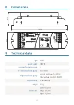
Страница 17: ...mber of output channels 1 0 10V output load capacity max 10mA relay output load capacity resistive load max 2A 250V AC inductive load max 0 5A 250V AC output sockets screw terminals weight 0 2kg dimensions width 143 4mm height 44 2mm depth 35 5mm 17 44 2 35 5 143 4 ...

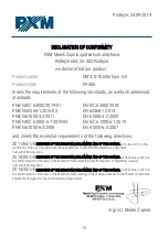
Страница 18: ... following directives 2011 65 UE DIRECTIVE OF THE EUROPEAN PARLIAMENT AND OF THE COUNCIL of 8 June 2011 on the restriction of the use of certain hazardous substances in electrical and electronic equipment Text with EEA relevance 2014 30 UE DIRECTIVE OF THE EUROPEAN PARLIAMENT AND OF THE COUNCIL of 26 February 2014 on the harmonisation of the laws of the Member States relating to electromagnetic co...

Отзывы: