


POWER VTX
®
WATER HEATER
21
PV500-68 06/16
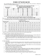
The following vent information is provided for use in design calculations, if needed.
Venting Specifications
Input MBtu/h
Combustion Air
Volume (cfm)
Max Vent Pressure
inches W.C.
500 170
1.0
750 225
1.0
1000 340
1.0
8.3 Vertical or Horizontal Vent Termination:
1. The vent terminal must have a minimum clearance of 4 feet (1.22 m) horizontally from, and in no case be
located above or below, unless a 4 foot (1.22 m) horizontal distance is maintained from electric meters, gas
meters, regulators and relief equipment.
2. The vent must terminate at least 3 feet (0.91 m) above any forced air inlet within 10 feet (3.05 m).
3. The vent shall terminate at least 4 feet (1.22 m) below, 4 feet (1.22 m) horizontally from or 1 foot (0.3 m) above
any door, window or building air inlet to the building.
4. The vent system shall terminate at least 1 foot (0.3 m) above grade and at least 1 foot (0.3m) above possible
snow accumulation levels and shall terminate at least 7 feet (2.13 m) above grade when located adjacent to
public walkways or gathering areas.
5. To avoid a blocked flue condition, keep the vent cap clear of snow, ice, leaves, debris, etc.
6. The vent must not exit over a public walkway, near soffit vents or crawl space vents or other areas where
condensate or vapor could create a nuisance or hazard or cause property or could be detrimental to the
operation of regulators, relief valves or other equipment.
7. A horizontal vent must extend one foot beyond the wall.
8. A horizontal vent terminal must not be installed closer than 3 feet (0.91m) from an inside corner of an L-shaped
structure.
9. A vertical vent must exhaust outside the building at least 3 feet (0.91m) above the point of the exit and at least 2
feet (0.61 m) above the highest point of the roof within a 10-foot (3.05 m) radius of the termination.
10. A vertical termination less than 10 feet (0.91 m) from a parapet wall must be a minimum of 2 feet (0.61 m)
higher than the parapet wall.
8.4 Combining
Category
IV
Vents
1. Combined POWER VTX
®
Category IV gas vent systems must incorporate an Exhausto, Tjernlund or US Draft
variable speed, modulating, mechanical draft inducer capable of maintaining the appropriate negative draft at
the end of the common flue, to assure that all water heaters in the combined vent system operate with a
negative draft.
Do not exceed negative 0.25
″
W.C.
See “Combining Vents with a Draft Inducer
”
illustration
below.
2. Combining the exhaust vents of multiple POWER VTX
®
condensing water heaters into a common, unpowered
or “gravity” vent is never recommended (i.e. venting as Category II). POWER VTX
®
water heaters are too
efficient and their flue products are too cold to generate the natural buoyancy required for such combined vent
systems to function reliably and safely.
3. The common mechanical draft vent system must be interlocked, so the water heaters will not begin operation
until the common mechanical draft vent system negative pressure is proved to be within the range of 0.04” and
0.25
″
W.C. See Section on
Remote Connections
for instructions for how to connect the proving circuit.


