background image

4-in-1 IRD User

’s Manual 

  31 / 38 

ASI X out bit-rate: 

Users can set TS output bit rate for the corresponding channel. 


After finishing the configuration, click 

to confirm. 


Parameters → Mux: 

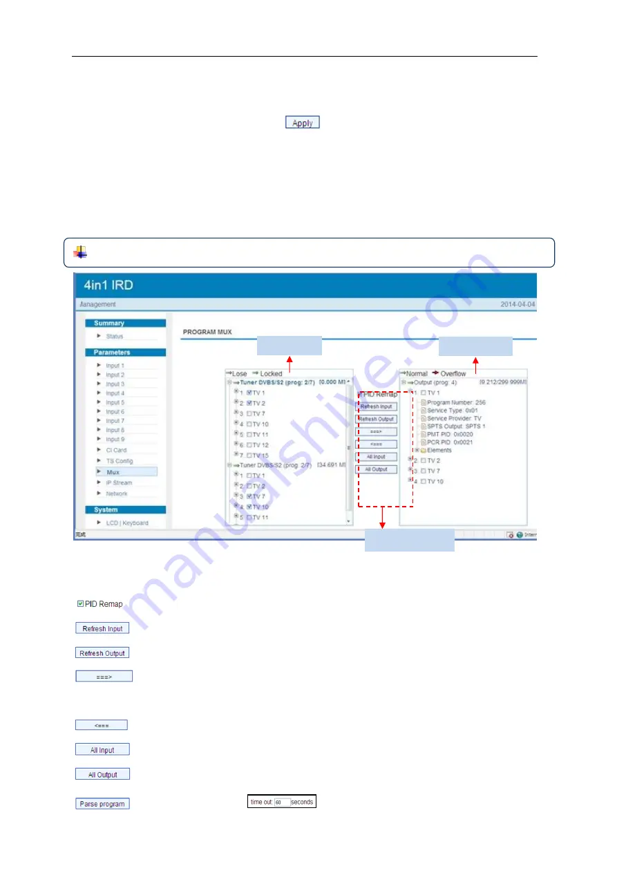
From the menu on left side of the webpage, clicking “Mux”, it displays the interface 

where users can configure the programs to be multiplexed. (Figure-9) 


NOTE: 

Programs selected to multiplex can only output through the 48 SPTS. 


Figure-9


Configure ‘Input Area’ and ‘Output Area’ with buttons in ‘Operation Area’. Instructions 
are as below: 

: To enable/disable the PID remapping 

  To refresh the input program information 

  To refresh the output program information 

  Select one input program first and click this button to transfer the selected 

program to the right box to output. 

  Similarly, user can cancel the multiplexed programs from the right box. 

  To select all the input programs 

  To select all the output programs 

  To parse programs 

time limitation of parsing input programs 

Input Area 

Output Area 

Operation Area 

Содержание MTRX

Страница 1: ...ital Tuner Streamer This Manual Apply to the MTRX 4 8 Tuner To IPTV Systems On 8 Tuners Systems The inputs are all assigned to the 8 Tuners Only and no asi Web NMS Version 1 03 Software 1 00 Hardware 0 40 ...

Страница 2: ... 2 Installation Guide 6 2 1 Acquisition Check 6 2 2 Installation Preparation 6 2 3 Wire s Connection 8 2 4 Signal Cable Connection 9 Chapter 3 Operation 11 3 1 LCD Menu Class Tree 11 3 2 General Setting 14 Chapter 4 Web based NMS Management 23 4 1 login 23 4 2 Operation 24 Chapter 5 Troubleshooting Error Bookmark not defined Chapter 6 Packing List Error Bookmark not defined ...

Страница 3: ...tly external power cords cables or additional remote control device To meet customers various requirements MTRX is also designed to de mux programs from any input and output TS over 48 SPTS 1 2 Features 4 Tuner inputs DVB C T T2 S S2 Optional 1 ASI 4 IP UDP input for de mux One CAM can decrypt multiple programs from Tuners ASI IP IP 48 SPTS over UDP and RTP RTSP output 4 groups of independent ASI ...

Страница 4: ...2 38 1 3 Specifications ...

Страница 5: ...0MHz Symbol rate 2 45Msps Signal Strength 65 25dBm Constellation 1 2 2 3 3 4 5 6 7 8 QPSK DVB S2 Input Frequency 950 2150MHz Symbol rate QPSK 1 45Mbauds 8PSK 2 30Mbauds Code rate 1 2 3 5 2 3 3 4 4 5 5 6 8 9 9 10 Constellation QPSK 8PSK Output IP 48 SPTS over UDP RTP RTSP 1000M Base T Ethernet interface unicast multicast ASI 4 groups BNC interface System Local interface LCD control buttons Remote m...

Страница 6: ...le CI 1 2 are designed to descramble tuner 1 2 ASI or IP 1 4 CI 3 4 are designed to descramble tuner 3 4 ASI or IP 1 4 1 5 Appearance and description 1 LCD Display 2 Indicators Area Lock 1 4 they light up when the tuner signal are properly connected Descram 1 4 they light up when the CI cards are properly inserted 3 Up Down Left Right Buttons Enter Key for confirmation Menu Key for backward Lock K...

Страница 7: ...to 4 2 Tuner Input 1 2 3 CAM CI Slots 3 4 Applied to descramble tuner 3 4 ASI input and IP input 1 to 4 4 Tuner Input 3 4 5 ASI output groups 1 4 6 ASI input port for de mux 7 NMS Port connect to PC for device management 8 DATA Port for IP stream input output 1000M 9 Power switch Fuse Socket Grounding Wire ...

Страница 8: ... steps The details of installation will be described at the rest part of this chapter Users can also refer rear panel chart during the installation The main content of this chapter including Checking the possible device missing or damage during the transportation Preparing relevant environment for installation Installing modulator Connecting signal cables Connecting communication port if it is nec...

Страница 9: ...time Pressure 86 105KPa Door Window Installing rubber strip for sealing door gaps and dual level glasses for window Wall It can be covered with wallpaper or brightness less paint Fire Protection Fire alarm system and extinguisher Power Requiring device power air conditioning power and lighting power are independent to each other Device power requires AC power 100 240V 50 60Hz Please carefully chec...

Страница 10: ...d grounding strip should be no less than 25mm2 2 2 5 Device Grounding Connecting the device s grounding rod to frame s grounding pole with copper wire 2 3 Wire s Connection The grounding wire conductive screw is located at the right end of rear panel and the power switch fuse power supply socket is just beside whose order goes like this power switch is on the left power supply socket is on the rig...

Страница 11: ...signal connections include the connection of input signal cable and the connection of output signal cable The details are as follows 2 4 1 MTRX 4 in 1 IRD Cables Illustration IP Input output Cable Illustration Tuner Cable Illustration ASI Input output Cable Illustration ...

Страница 12: ...4 in 1 IRD User s Manual 10 38 ...

Страница 13: ...EFT RIGHT Choose and set the parameters UP DOWN Modify activated parameter or paging up down when parameter is inactivated ENTER Activate the parameters which need modifications or confirm the change after modification MENU Cancel current entered value resume previous setting Return to previous menu LOCK Lock the screen cancel the lock state After pressing the lock key the LCD will display the cur...

Страница 14: ...rogram 3 1 6 Rom Version 3 1 7 Card Status 3 1 8 Descramble Error Same content with Tuner 1 above Same content with Card A above Input IP Input Port Multicast IGMP Snooping Service IP 2 5 ASI 2 5 1 TS Lock 2 5 2 Parse Program 2 5 3 Select Program 2 6 IP 2 6 1 IP Config 2 6 2 Mux Program TS Lock Parse Program Select Program 2 3 Tuner DVBS S2 2 2 Tuner DVBS S2 2 7 IP 2 8 IP 2 9 IP 3 3 Card C 3 4 Car...

Страница 15: ... 3 Gateway 6 4 MAC Address 6 6 Reset Password 6 5 Web NMS Port 4 1 TS output bitrate 5 IP Stream 5 4 Output Protocol 5 5 SPTS 1 5 3 Gateway Data Enable Null PKT Filter Output IP Output Port Bitrate 5 1 Service IP 5 2 Subnet Mask 5 6 SPTS 2 5 52 SPTS 48 SPTS 2 48 have the same submenus with SPTS 1 above 7 9 Version 4 3 ASI 1 out bitrate 4 4 ASI 2 out select 4 5 ASI 2 out bitrate 4 6 ASI 3 out selec...

Страница 16: ...g to the 7 directions displayed on the LCD User can press UP DOWN and RIGHT LEGT buttons to specify menu item and then press ENTER to enter the submenus as below 3 2 1 Status Alarm The alarm indicator will turn on if there is no signal inputting or outputting bit rate overflows User then can enter this menu to check the error type Otherwise it shows the system is normal Uptime It displays the work...

Страница 17: ...according to rear panel It displays as below Tuner Parameters Users can enter this menu to configure the tuner parameters separately to receive the tuner programs Mux Program Users can parse the Tuner input program list and select programs to out in this menu NOTE Multiplexed programs can only be output through IP 48 SPTS Tuner Parameters Satellite frequency LNB frequency Symbol rate LNB Voltage 2...

Страница 18: ...uner 1 or 2 Mux Program 0 7 1 TV 1 X 1 7 represents there are all 7 programs in the list and 1 program has been selected to mux out through ASI Mux Program 0 7 1 TV 1 Mux Program 0 7 1 TV 1 Mux Program 1 7 1 TV 1 Process of selecting programs to output through front panel to cancel program output to output the program a symbol indicating the corresponding program has been selected to output X a sy...

Страница 19: ...ENTER key to enter 3 CI Card to configure the 4 cards respectively Press ENTER key to enter Card A or Card B C D Max Bit rate CI Max Bitrate options range from 48 108Mbps Move the triangle to select a value as principle Actual Input Bitrate Max Bitrate CI Max decrypting capacity Off V2 and V3 Optional Max Bitrate 48 Mbps Input IP Input Port Multicast IGMP Snooping Service IP 2 5 1 TS Lock 2 5 2 Pa...

Страница 20: ...to descramble tuner 3 4 ASI input and IP input 1 to 4 Card Error Check Users can decide whether to enable or disable the card error check function in this menu Parse Program Users can read the quantity of programs parsed from the de scrambled channel Descramble Program Users can select program s from the searched out programs to descramble The quantity to be descrambled depends on the CAM CI perfo...

Страница 21: ...ith 4 pairs of ASI out ports Each pair can transfer one channel of tuner or one channel of IP content of corresponding channel For instance user can select content from tuner 1 or IP 1 to output through ASI 1 Tuner 1 IP 1 To transfer programs from Tuner 1 without mux Rom Version 4 2 4 0 Card Status Normal Descramble Error Normal To transfer programs from IP without mux 4 1 TS output bitrate 4 2 AS...

Страница 22: ...IRD supports 48 SPTS over IP UDP RTP RTSP output Users can set the IP out parameters in this menu TS ID 00001 ON ID 00001 ASI X out bit rate 054 Mbps 5 1 Service IP 5 2 Subnet Mask 5 3 Gateway 5 4 Output Protocol 5 5 SPTS 1 5 6 SPTS 2 5 7 SPTS 3 5 8 SPTS 4 5 49 SPTS 45 5 50 SPTS 46 5 51 SPTS 47 5 52 SPTS 48 5 1 5 4 To configure the general parameters for the IP out 5 5 5 52 Enter each sub menu to ...

Страница 23: ...arately set corresponding parameters NMS IP 192 168 000 136 Subnet Mask 255 255 255 000 Gateway 192 168 000 001 MAC Address 201012345678 Reset Password Yes NO Web NMS Port 00080 The IP address for connecting the device to PC 6 1 NMS IP 6 2 Subnet Mask 6 3 Gateway 6 4 MAC Address 6 5 Web NMS Port 6 6 Reset Password 7 1 Save Config 7 2 Load Saved CFG 7 3 Factory Reset 7 4 LCD Time out 7 5 Key Passwo...

Страница 24: ...figuration Press DOWN UP key to select a time out for the LCD lighting duration 5 120 seconds To set a 6 digit password for unlocking the keyboard Choose Yes to lock the keyboard then the keyboard will be locked and cannot be applicable It is required to input the password to unlock the key board This operation is one off User can view the serial number of this device It is read only and unique It...

Страница 25: ... the device with net cable and use ping command to confirm they are on the same network segment I G the PC IP address is 192 168 99 252 we then change the device IP to 192 168 99 xxx xxx can be 1 to 254 except 252 to avoid IP conflict Use web browser to connect the device with PC by inputting the device s IP address in the browser s address bar and press Enter It will display the Login interface a...

Страница 26: ...tem information and working status Figure 2 Language shift area User can click any item here to enter the corresponding interface to check information or set the parameters System information Input information of the 4 satellite signals ASI and 4 IP streams Green light indicates the corresponding signal is properly locked Otherwise the light is red Output information of the TS ...

Страница 27: ...uner input parameters separately Figure 3 Figure 3 Parameters Input 5 ASI Input Input 5 refers to the ASI source this page is not applicable as it does not need to configure ASI signal Figure 4 Configure tuner parameters in this area according to your signal source to receive programs Click Apply button to apply the input data to start receive signals Tuner signal input 1 4 ASI input IP signal inp...

Страница 28: ...f the webpage clicking Input 6 or Input 7 8 9 it displays the interface where users can configure the IP input parameters separately Figure 5 Figure 5 Click Apply button to apply the input data to start receive signals Configure IP parameters in this area according to your signal source to receive programs ...

Страница 29: ...User s Manual 27 38 Parameters CI Card MTRX supports 4 CI cards Card A B C and D to descramble programs from encrypted RF ASI or IP Users can click and enter CI Card to configure the 2 cards respectively Figure 6 ...

Страница 30: ...put Bitrate Max Bitrate CI Max decrypting capacity Input TS Mode MTRX has 9 signal sources Tuner 1 4 ASI and IP 1 4 One CI card can applied to descramble one channel input signal from the 9 signal sources Skip CI card means to skip the card which is used for FTA stream NOTE Card A B are designed to descramble tuner 1 2 ASI input and IP NOTE Card Selection Area ...

Страница 31: ...CI card parameters click button to apply the input data and then click button to parse programs from the channel selected in Input TS Mode The searched out programs will be listed in the Descramble box below Figure 7 Figure 7 Check the program s to be descrambled and click button to start descrambling the checked program s The program quantity to be descrambled will depend on the CAM CI performanc...

Страница 32: ...with 4 pairs of ASI out ports Each pair can transfer one channel of tuner or one channel of IP content of corresponding channel For instance user can select content from tuner 1 or IP 1 to output through ASI 1 Number before slash indicates the programs which have been descrambled Number behind slash indicates the whole programs from the selected channel Users can also read the program information ...

Страница 33: ...gh the 48 SPTS Figure 9 Configure Input Area and Output Area with buttons in Operation Area Instructions are as below To enable disable the PID remapping To refresh the input program information To refresh the output program information Select one input program first and click this button to transfer the selected program to the right box to output Similarly user can cancel the multiplexed programs...

Страница 34: ...am in the output area For example when clicking it triggers a dialog box Figure 10 where users can input new information Figure 10 Input new data and click Save button at last to confirm the modification Parameters IP Stream NOTE This device supports 48 SPTS IP out Users can enable and select the program output via SPTS here ...

Страница 35: ... displays the interface where users can configure the SPTS out parameters Figure 13 Figure 13 Parameters Network From the menu on left side of the webpage clicking Network it will display the screen as Figure 14 where to configure the network parameters for the device Figure 14 System LCD Keyboard ...

Страница 36: ... panel Figure 15 System Password From the menu on left side of the webpage clicking Password it will display the screen as Figure 16 where to set the login account and password for the web NMS Figure 16 System Save Restore From the menu on left side of the webpage clicking Save Restore it will display the screen as Figure 17 where to save or restore your configurations ...

Страница 37: ...IRD User s Manual 35 38 Figure 17 System Backup Load From the menu on left side of the webpage clicking Backup Load it will display the screen as Figure 18 where to backup or load your configurations Figure 18 ...

Страница 38: ...the webpage clicking Firmware it will display the screen as Figure 19 where to update firmware for the device Figure 19 System Reboot From the menu on left side of the webpage clicking Reboot it will display the screen as Figure 20 where to restart the device manually Figure 20 ...

Отзывы: