Page 1 / 7
PV500-40 04/2013
WATER HEATER
ELECTRONIC CONTROLLER
USER MANUAL
PVI Industries, LLC • 3209 Galvez Dr • Fort Worth, Texas 76111 • 800-784-8326
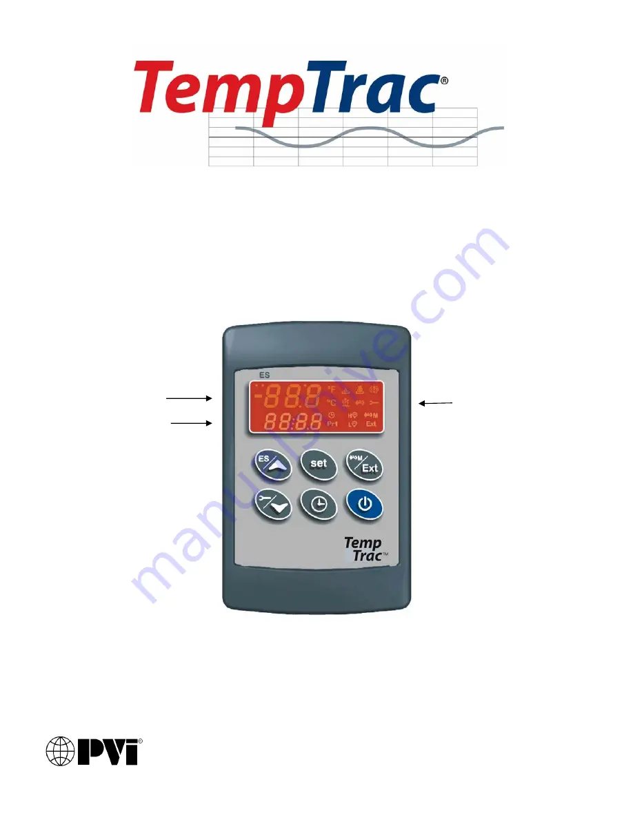
UPPER LED READOUT
LOWER LED READOUT
LED
ICONS
Страница 1: ...Page 1 7 PV500 40 04 2013 WATER HEATER ELECTRONIC CONTROLLER USER MANUAL PVI Industries LLC 3209 Galvez Dr Fort Worth Texas 76111 800 784 8326 UPPER LED READOUT LOWER LED READOUT LED ICONS ...
Страница 2: ...NS To lock and unlock the keyboard To enter the programming mode To exit the programming mode 1 3 LED ICON LEGEND LED MODE Function ON Temperatures are displayed in degrees Fahrenheit ON Temperatures are displayed in degrees Celsius Flashing Call for heat time delay or remote enable disable is in standby disabled ON Call for heat is on Flashing Second stage time delay On 2 stage units only ON Seco...
Страница 3: ...ure All of the display information described above is available for monitoring through the optional MODBUS RTU interface 1 5 LOWER LED READOUT The default display of this readout is the temperature sensed at Probe 1 Probe 1 will be inserted into the appropriate area of the storage tank to provide effective temperature response for the heat source this may not be at the top of the tank Refer to you...
Страница 4: ...mperature or operating parameters that the user can adjust St 1 This setpoint temperature should be considered the F or C temperature threshold to activate the energy source The setpoint corresponds directly to the temperature sensed by probe 1 The St 1 setpoint is programmed as an absolute temperature for example 120 F St 2 This setpoint corresponds to either the threshold for second stage burner...
Страница 5: ...procedure The set value is stored even when the procedure exits due to the 15 second expiration 2 2 HOW TO LOCK THE KEYBOARD 1 Push and hold the keys for more than 3 seconds 2 The POF message will be displayed and the keyboard is locked At this point it is only possible to view the set point 3 Repeat step 1 to unlock the keyboard 2 3 HOT KEY PROGRAMMING FOR FACTORY SUPPORTED FIELD REPROGRAMMING To...
Страница 6: ... alarm LED icon is also illuminated Message Cause Results of alarm condition P1 Probe 1 failure Call for heat and burner second stage interrupted modulation output will be the PP4 parameter generally low fire P2 Probe 2 failure Output 3 is open P3 Probe 3 failure Dynamic reset of Set1 disabled Outdoor reset is disabled if used or Flue gas temperature protection is disabled if used HA High temperat...
Страница 7: ...m condition still present 3 2 ALARM RECOVERY 1 Probe failure alarm automatically ends after normal operation is re established Check connections before replacing the probe 2 Temperature alarms HA and LA automatically stop as soon as probe 1 senses temperatures within normal operating parameters 3 Digital input 2 3 alarms recover when condition s listed above are normalized and any button is presse...