background image

Nixie Clock Kit ' Maestro’ 


ISSUE 1 (06 December 2012)


www.pvelectronics.co.uk


- 12 - 

Setting the Time and Date: 

From time display mode, press and hold ‘SET’ button for 2 seconds until 
the seconds digits are highlighted. 
Press the ‘ADJ’ button to reset seconds to zero. 
 
Briefly Press ‘SET’ again and the hours will be highlighted 
Press the ‘ADJ’ button to set the minutes. 
 
Briefly Press ‘SET’ again and the hours will be highlighted.  
Press the ‘ADJ’ button to set the hours. 
 
Proceed in this fashion to set the calendar: Year, Month and Day. 
 
Finally, briefly Press ‘SET’ again to revert to normal clock operation. 
 

Showing Date: 

From time display mode, briefly press ‘SET’ button. Date will be shown 
for 5 seconds, then revert to time display. 
 

Auto Date Display: 

Setting parameter (18) to ‘1’ will enable auto display of date between 50 
and 55 seconds past each minute. 
 

Night Blanking Override: 

During programmed night blanking, the blanking may be overridden to 
see the time by briefly pressing the ‘SET’ button. Tubes will remain lit for 
the period defined in parameter (8). 
 

Setting Alarm: 

Press the ‘ALARM’ Button. The seconds digits show the on / off status of 
the alarm: 00 or 01 (off or on). 
Set on / off status, then minutes followed by hours by using the ‘ALARM’ 
and ‘ADJ’ buttons. When set, the alarm LED will also light. 
 

Cancelling Alarm

:


Press ‘ALARM’ briefly to cancel alarm and enter snooze mode, or a longer 
press until the clock bleeps, to cancel snooze. Alarm remains set for the 
next day. 
 

Rapid DST Adjustment


Press ‘DST’ briefly to toggle between DST and standard time. The 
Indicator shows whether DST mode is active or not.  
Note, that GPS time data does not contain DST information, so the DST 
status will need to be set manually in GPS sync mode as well as manual 
time-set mode. 

Содержание Nixie Maestro

Страница 1: ...Nixie Clock Kit Maestro ISSUE 1 06 December 2012 www pvelectronics co uk 1 Assembly Instructions and User Guide Nixie Clock Type Nixie Maestro ...

Страница 2: ...Nixie Clock Kit Maestro ISSUE 1 06 December 2012 www pvelectronics co uk 2 REVISION HISTORY Issue Number Date Reason for Issue 1 06 December 2012 New document ...

Страница 3: ...able leading zero blanking Five programmable neon colon settings Flashing AM PM indication illuminated AM PM indication both flashing both on both off Seconds can be reset to zero to precisely the set time Programmable night mode blanked or dimmed display to save tubes or prevent sleep disturbance Rear Indicator LEDs dim at night to prevent sleep disturbance Weekday aware Master Blank function to ...

Страница 4: ... generated by this circuit can give a potentially LETHAL ELECTRIC SHOCK DISCLAIMER This product is supplied as a kit of parts intended only for suitably qualified electronic engineers who are suitably qualified and experienced in electronics assembly and are familiar with safe procedures for working with high voltages The supplier his agents or associates accept no liability for any damage injury ...

Страница 5: ... of nail clippers works very well for this function Wire strippers TIP A small pair of scissors is quite suitable Multimeter for voltage tests and for identifying the resistors 2 2 Materials you will need Solder lead tin solder is highly recommended USE LEAD TIN SOLDER Lead free solder as now required to be used in commercial products in Europe has a much higher melting point and can be very hard ...

Страница 6: ... Vertical push switch SET ADJ ALARM DST 4 5mm Yellow LED P1 P2 P3 3 3mm Orange LED P4 P5 P6 P7 4 500mA Fuse F 1 It is recommended that the kit is checked against the list above to ensure all parts are present before commencing assembly Don t be alarmed if there are some extra components as some component bags are shared between different kit types Please note the fuse will look like the picture be...

Страница 7: ...nto the hole marked or the hole with the white circle around it 2 The electrolytic capacitors are polarised The side of the capacitor with the lighter band marked goes next to the cross hatched marking on the PCB 3 CAP2 the time backup capacitor needs to be placed flat against the PCB Use a small length of trimmed lead from another component to extend one lead so that it can be place flat Also not...

Страница 8: ...ronics co uk 8 5 POWER SUPPLY You will need to provide a suitable regulated power supply 500mA or more current capability 12V DC 5 5mm plug with 2 1mm inner centre positive A suitable power supply for USA Canada Japan and Australia is available in our web store ...

Страница 9: ...will become highlighted Continue holding the button a further 2 seconds until the clock displays in this format 00 XX 99 The 99 in the seconds digits tells you that you are in the configuration menu In configuration mode the hours digits diplay the current parameter being adjusted and the minutes digits display the current value stored against the parameter For each parameter and referring to the ...

Страница 10: ...dication flashing 1 AM PM Indication illuminated 2 Both flash default 3 Both illuminated 4 Both off 11 Colon neons during night dimmed mode 2 0 AM PM Indication flashing 1 AM PM Indication illuminated 2 Both flash 3 Both illuminated default 4 Both off 12 Radio time signal source 0 No Radio Time source default 3 1 Reserved 2 Reserved 3 Reserved 4 GPS 13 GPS Baud rate 0 4 8 Kbps default 1 9 6 Kbps 2...

Страница 11: ...ck on weekends eg clock is in office or during office hours eg clock is at home Complete HV shutdown to save power and tube life 2 Night time neons mode is active when night mode is set to dim During night time blanking the tubes AND neons are disabled 3 Clock is fully functional without GPS synchronisation Set time manually 4 Enter your time zone offset from the synchronisation source Note that G...

Страница 12: ...le auto display of date between 50 and 55 seconds past each minute Night Blanking Override During programmed night blanking the blanking may be overridden to see the time by briefly pressing the SET button Tubes will remain lit for the period defined in parameter 8 Setting Alarm Press the ALARM Button The seconds digits show the on off status of the alarm 00 or 01 off or on Set on off status then ...

Страница 13: ...r than an accurate time standard You can finely adjust the timekeeping by setting configuration parameters 20 and 21 We recommend to precisely set the clock against a known accurate clock and then record the time drift in seconds after 5 full days 120 hours Program this value into parameter 20 Set parameter 21 to 0 to slow down the clock and to 1 to speed up the clock ...

Страница 14: ...g effect at your choice of speed 7 1 Entering RGB LED menu Press and hold the DST button until the display shows 00 0 00 The first minutes tube will not be lit For each hour 0 23 you can set a custom colour Each custom colour can have your choice of RED GREEN and BLUE values from 0 colour off to 8 maximum brightness Mix the colours using the SET ADJ ALARM buttons Use low values 1 2 and 3 for low b...

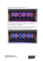
Страница 15: ...onics co uk 15 Colours are displayed live during RGB menu In the example above between 8 and 9 hours the LEDs will be purple 8 red 0 green and 8 blue In the example below between 19 and 20 hours the LEDs will be blue with a hint of green 0 red 2 green and 8 blue ...

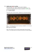
Страница 16: ...ed hour The speed of the cycling will then be governed by the GREEN value 0 very slow change 9 very fast change This auto colour cycling mode is explained in the picture below Red 9 therefore Auto Colour Cycling is enabled for 12 13 hours Green 3 so speed is 3 Blue value has no effect Note The colours do not cycle live during Auto Colour Cycling setup The cycling starts only during normal time and...

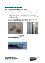
Страница 17: ...using our Micro GPS ensure the baud rate in parameter 13 is value 0 Set parameters 14 and 15 for the hours and minutes your time zone is offset from UTC This is usually only whole hours Set parameter 16 to identify whether the offset is minus 0 or positive 1 of UTC The clock has been designed for and tested with our Micro GPS Receiver available separately from PV Electronics ...

Страница 18: ... Synchronisation not enabled parameter 12 0 LED is permanently off GPS Synchronisation enabled parameter 12 4 The LED will be ON if the clock has synchronised in the last two hours slowly flashing if the last synchronisation was between 2 hours and 24 hours ago and off if the last synchronisation is older than 24 hours ...

Отзывы: