background image

STEP 4 –


LED and Battery Clip

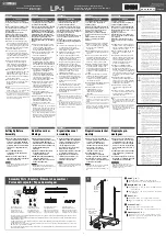
Solder two wires to the LED 

connection (red to the “+” sign).  

Then,  solder then to the LED (the red 

wire is connected to the longer pin). 


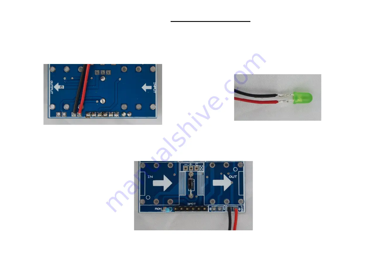
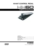
Solder the battery clip, connecting the red wire to the “+” sign:


Содержание RC Booster

Страница 1: ...RC BOOSTER...

Страница 2: ...we have put together a few links that detail some of the aspects explained in this manual and that we think you can find helpful Kit PuzzleKit general manual Reading resistor and capacitor values Als...

Страница 3: ...00k 1 R17 6 8k 1 R18 15k Capacitors 13 1 C1 47n 2 C2 C9 1u 1 C10 100n 1 C3 150p cer 2 C5 C8 4 7n 2 C6 C7 33n 4 C11 C12 C13 C14 10u electro 0 C4 Not used leave unconnected Transistors 2 2 Q1 Q2 2SC1815...

Страница 4: ...RC BOOSTER Part Placement...

Страница 5: ...RC BOOSTER STEP BY STEP GUIDE...

Страница 6: ...e values check out our Reading Part Values tutorial Resistors 31 2 R1 R3 1M 4 R2 R4 R10 R11 10k 1 R5 5 1k 3 R6 R8 R9 20k 2 R7 R28 100k 2 R12 R13 4 7M 5 R14 R18 R19 R23 R24 330 3 R15 R21 R25 4 7k 4 R16...

Страница 7: ...IC sockets Pin header First of all place the IC sockets without the ICs Pay attention to the orientation The small notch in the socket should be oriented as indicated in the PCB Then connect the 6 pin...

Страница 8: ...lues check out our Reading Part Values tutorial Pay attention to the orientation as well as to the polarity for electrolytic capacitors Capacitor List 3 C1 C8 C9 22n 1 C2 220n 2 C3 C10 1u electro 1 C4...

Страница 9: ...LED and Battery Clip Solder two wires to the LED connection red to the sign Then solder then to the LED the red wire is connected to the longer pin Solder the battery clip connecting the red wire to t...

Страница 10: ...STEP 5 DC Power Jack wires Solder three wires about 5cm each to the DC connection as shown don t solder anything to the other end yet...

Страница 11: ...STEP 6 Audio Jacks Now solder the audio jacks to the board DC battery and led wires are not present to make it clearer...

Страница 12: ...ces of wire for each potentiometer you have to solder i e 9 pieces for 3 potentiometers Then solder them to each lug The first lug is the one in the left in top view the black wire in the picture Here...

Страница 13: ...Then solder them to the board like in the picture in the left and then place the board inside the enclosure...

Страница 14: ...STEP 8 DC Power Jack First of all insert the DC jack in the enclosure and tighten the nut Then solder the three wires from the DC connector in the board to the DC jack as follows...

Страница 15: ...ttention the pins and the 3PDT must be soldered to the same side of the PCB adapter the one labeled buttons and 3PDT on this side B Solder the 3PDT Now solder the 3PDT to the PCB and remove all the nu...

Страница 16: ...STEP 10 Connect the 3PDT STEP 11 Your pedal is finished By now you should have a fully functional effect pedal we hope you enjoy it...

Отзывы: