


6
7
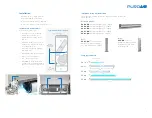
Installation
Installation in Unit Ventilator
Follow these instructions:
1) Identify location to install the
Fighter. Ideally install the
Fighter in between the blower
and coil.
2) Install lamp clips into the sheet
metal using sheet metal screws
or self tapping screws.
3) Install lamp by gently pushing
into lamp clips.
4) Install ballast and plug into lamp.
5) Connect power supply to
120 – 277V supply mains.
6) CAUTION: To avoid accidental
UV exposure do not apply power
until unit ventilator is fully closed.
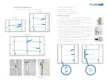
Installation for On-Coil Disinfection
The modular mounting rack for the Fighter assembly includes the
following items:
• Handle with care; fragile material
• Inspect packaging for damage
• Inspect unit immediately for damage
• Remove the protective film from the device
Vertical Upright
VU-20-XX
= Vertical upright, 19.69" length
VU-32-XX
= Vertical upright, 31.5" length
VU-43-XX
= Vertical upright, 42.5" length
VU-51-XX
= Vertical upright, 51.2" length
VU-63-XX
= Vertical upright, 63" length
Joint
VU-J-XX
= Joint for
vertical upright, includes
8 square nuts M5 and
8 screws M5x6
Feet
VU-FT-XX
= Foot for vertical
upright, includes 2 square
nuts M5 and 2 screws M5x6
FR-16
FR-25
FR-40
FR-60
FR-90
12.5"
11.2"
21.5"
20.2"
16.4"
23.6"
22.2"
35.8"
34.4"
17.8
Clip Distance
Lamp Type and Sizes
Filter
Fan
Heat
Radiant
Air
Intake
Fighter
Application
Options
Air Output
Typical Unit Ventilator Diagram
Power Supply
Lamp Clip
7


