Edition from 23.11.2017
5
PLD442.
Microstepping stepper motor driver
www.purelogic.ru
8 (800) 555 63 74
04. Driver functional capabilities
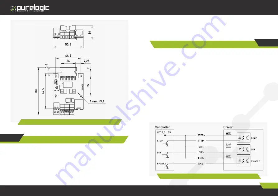
Fig. 1.
Stermotor driver PLD442 dimensions
05
Connectors, switch-overs and indication assignment
XP1 – clip connector of driver power supply
XP2, XP3, XP4 – clip connectors of input signals connection
XP5 – connector (RJ45 type of input signals connection)
XP6, XP7 – clip connectors of stepper motor connection
XP8 - mode switching contacts
LED1 – POWER signal indication.
LED2 – ERROR signal indication.
LED3 – ENABLE signal indication.
LED4 – STEP signal indication.
LED5 – DIR signal indication.
Controlling signals connection to stepper motor driver
Controlling signals connection
PLD442 driver controls a stepper motor using standard signals
STEP/DIR/ENABLE.
STEP/DIR/ENABLE signals are allocated to connectors XP2, XP3,
XP4 and RJ45 — XP5-type and are galvanically separated from the
controller.
As STEP signal frequency is increased, LED4 intensity also changes.
The scheme of differential input device and connection method to
the controller with outputs ‘open collector’ type is shown in fig.2.
STEP signal characteristics are working voltage 3 ... 5V, current
consumption is 20mА, min signal duration is 10 ms. Stepper motor step
is performed on signal’s back edge.
DIR signal’s characteristics – working voltage 3 ... 5V, current
consumption is 20mА, action time is 200 ns before/after STEP’s front
edge.
06
Fig. 2.
Differential inputs device


