


www.pulsar.pl
AWZ637
7
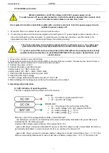
RED LED:
on
– the PSU is supplied with 230 V AC
off
– no 230 V AC supply
GREEN LED:
on
– DC voltage in the AUX output of the PSU
off
– no DC voltage in the AUX output of the PSU
on - battery voltage U
BAT
> 11,5 V
off - battery voltage U
BAT
< 11,5 V
2.2 Installation procedure.
Before installation, cut off the voltage in the 230 V power-supply circuit.
To switch power off, use an external switch, in which the distance between the contacts of all
poles in the disconnection state is not less than 3 mm.
It is required to install an installation switch with a nominal current of 6 A in the power supply circuits
outside the power supply unit.
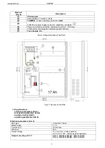
1. Mount the PSU in a selected location and connect the wires.
2. Connect the ground wire to the terminal marked by the earth symbol
(power supply module connector). Use a
three-core cable (with a yellow and green
protection wire) to make the connection. Lead the cables to the
appropriate terminals of the connection board through the insulating bushing.
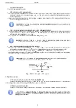
The shock protection circuit shall be performed with a particular care, i.e. the yellow and
green wire coat of the power cable shall stick to one side of the terminal - marked with
‘
‘
symbol on the PSU enclosure. Operation of the PSU without the properly made and fully
operational shock protection circuit is UNACCEPTABLE! It can cause a device failure or an
electric shock.
3. Connect the controller to wire with DC plug
4. Connect the receivers' wires to the AUX and COM connectors of the fuse module. If necessary, the values of fuses in
the LB4 module can be selected, but 1.5 A should not be exceeded.
5. Connect the power (~230 V)
6. Connect the battery (mind the colours):
- battery output (+V): BAT+ cable / red,
- battery output (0V): BAT
– cable / GND / black.
7. Check the PSU operation indicator: green LED.
8. Check the PSU output voltage:
- the PSU voltage without load should amount to U=13,8 V DC.
9. After installing and checking proper working, the enclosure can be closed.
3. Operating status indication.
3.1 LED indication of operating status.
The PSU is equipped with two diodes on the front panel:
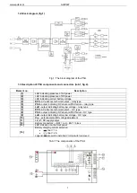
Moreover, the PSU is equipped with 3 LEDs on the PCB board:
- red LED (Fig.2, element 1) normal status (AC power): permanently illuminated. AC power absence is
indicated by the AC diode going out.
Caution! LED indicates power absence if the outage lasts >10 s.
- green LED (Fig.2, element 2) indicates DC power at the PSU output. Under normal status the diode is
permanently illuminated. In case of a short circuit or an overload, the diode is off.
- green LED (Fig.2, element 3) indicates battery voltage level. Under normal status (U
BAT
> 11,5 V) the
diode is permanently illuminated. In case of decrease of battery voltage (U
BAT
< 11,5 V) the diode is off.


