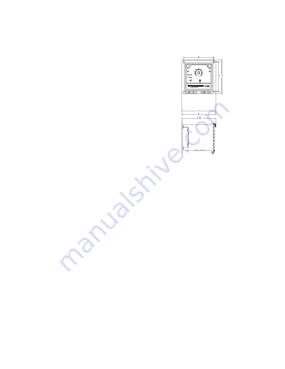
B. MOUNTING:
Mount Controller vertically on a wall or a permanent
vertical support with adequate lighting and at a comfort-
able level (Refer to Fig. 2, Controller Dimensions).
C. ACCESSORIES:
(Available through your Pulsafeeder distributor or sales
representative, but not included as standard)
Boiler Conductivity Timed Sample:
1. Blowdown valve, solenoid and strainer or motor oper-
ated ball valve.
2. Needle valve or orifice union and plates for throttling
blowdown.
3. A full-port gate valve for isolation of blowdown
assembly.
4. A flush valve for sensor.
Boiler Conductivity Continuous Sample:
1. Blow down valve, solenoid and strainer or motor
operated ball valve.
2. Two needle valves or two orifice unions and plates for throttling blowdown.
3. A full-port gate valve for isolation of blowdown assembly.
4. A flush valve for sensor.
D. PLUMBING:
A flow rate of at least 1-3 gpm (gallons per minute)
at the electrode is required for proper operation.
Install hand valves on both sides of electrode for easy removal and periodic
maintenance.
Direction of flow should be in line with the arrow on probe assembly. Take
time to review Fig. 1, Typical Installation Diagram, and note locations of hand
valves, etc. for proper operation and maintenance of all components in the sys-
tem loop. The throttling valve must be adjusted so that water flows across the
probe, not steam.
5
Fig. 2, Controller Dimensions


