background image


W W W . P S S O . D E  

24


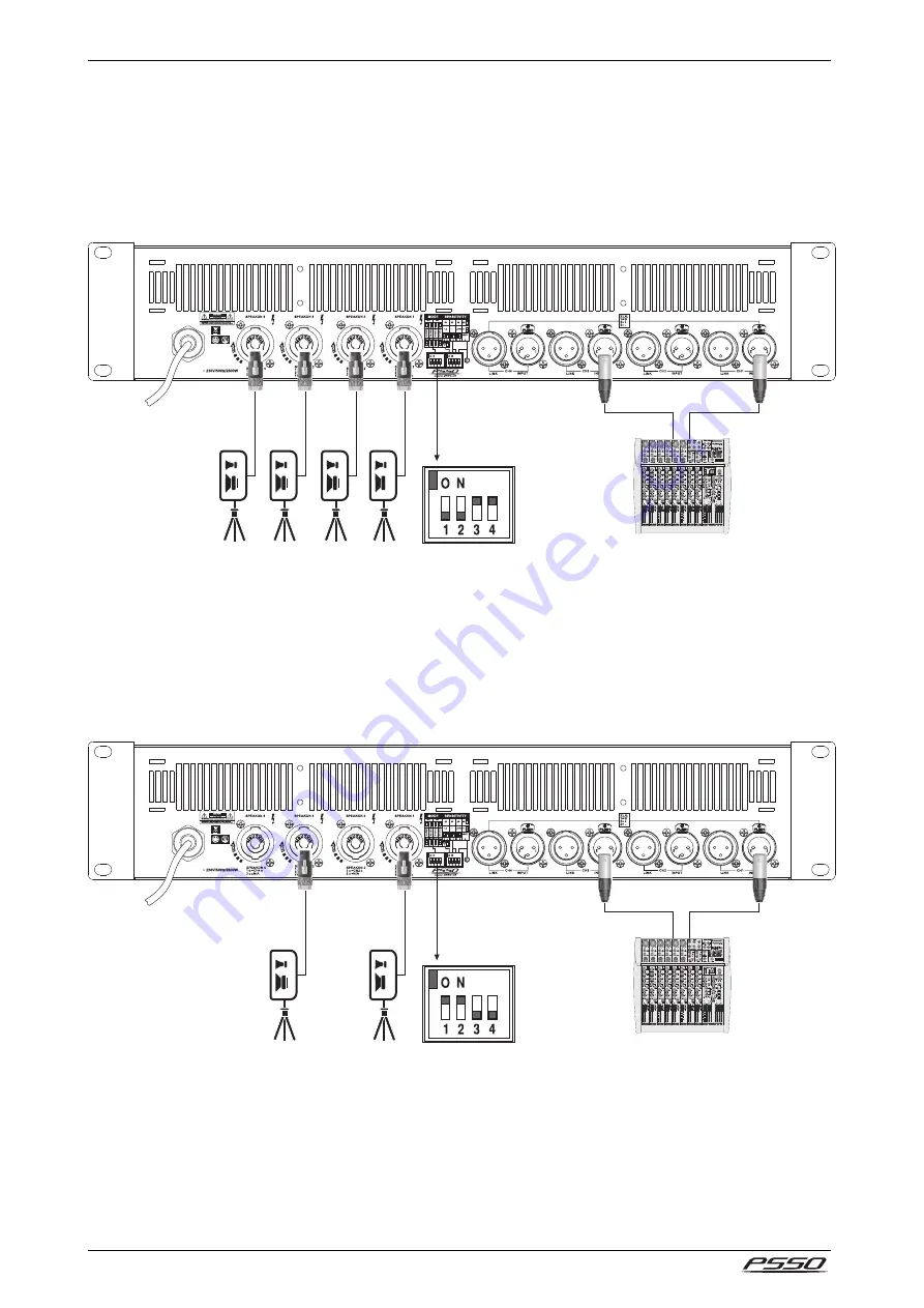
Parallel Operation  

In parallel operation, channels 1 and 2 and channels 3 and 4 respectively receive the same input signal. A 
signal at the input of channel 2 and channel 4 is ignored. The volume is separately adjusted for all outputs. 
This way, PA amplification can provided e.g. for several rooms using the same mono signal while adjusting 
the  volume  independently.  For  this  operating  mode,  set  the  DIP  switches 

MODE  3  and  4 

to  their  upper 

position.  Note:  At  channel  1  and  channel  3,  it  is  possible  to  take  off  the  signal  of channel  2  and  channel  4 
respectively from pins 2+/2-. 


Bridge Operation 

In bridge mode, channels 1 and 2 and channels 3 and 4 are bridged and therefore provide higher power than 
a single channel. Thus, the voltage at the outputs of channel 1 and channel 3 is doubled and subsequently 
the output impedance. A signal at the  input of channel 2 and channel 4 is ignored. The volume is adjusted 
together for both outputs with the control of channel 1 and channel 3. For this operating mode, set the DIP 
switches 

MODE 1 and 2 

to their upper position. Note: In bridge mode, the output signal is provided at pins 

1+/2-. 


Connection to the Mains 

Finally connect the device to the mains with the mains cable. The ON indicator lights up.  


Содержание QCA 10000

Страница 1: ... A L U S E R M A N U A L U S E R M A N U A L U S E R M A N U A L B E D I E N U N G S A N L E I T U N G B E D I E N U N G S A N L E I T U N G B E D I E N U N G S A N L E I T U N G B E D I E N U N G S A N L E I T U N G ...

Страница 2: ...autsprecherausgänge über verriegelbare Neutrik Speakon Buchsen Robustes Stahlgehäuse mit Aluminium Frontplatte Rackeinbau mit 2 Höheneinheiten 4 4 4 4 channel PA Amplifiers with Integrated SMPS channel PA Amplifiers with Integrated SMPS channel PA Amplifiers with Integrated SMPS channel PA Amplifiers with Integrated SMPS The 4 channel PA amplifiers of the QCA series offer ultra high output power p...

Страница 3: ...el einstellen 13 Schutzschaltungen 13 8 PROBLEMBEHEBUNG 14 9 REINIGUNG UND WARTUNG 14 10TECHNISCHE DATEN 15 Table of Contents 1 INTRODUCTION 16 2 SAFETY INSTRUCTIONS 16 3 OPERATING DETERMINATIONS 18 4 OPERATING ELEMENTS CONNECTIONS 20 Front Panel 20 Rear Panel 20 5 RACK INSTALLATION 21 6 CONNECTIONS 22 Inputs 22 Feed through Output 22 Speaker Outputs 22 Stereo Operation 23 Parallel Operation 24 Br...

Страница 4: ...icherheitstechnisch einwandfreiem Zustand verlassen Um diesen Zustand zu erhalten und einen gefahrlosen Betrieb sicherzustellen muss der Anwender unbedingt die Sicherheits hinweise und die Warnvermerke beachten die in dieser Gebrauchsanweisung enthalten sind Bei Schäden die durch Nichtbeachtung dieser Bedienungsanleitung verursacht werden erlischt der Garantieanspruch Für daraus resultierende Folg...

Страница 5: ...e Abschaltung vorgenommen werden Wenn der Netzstecker oder das Gerät staubig ist dann muss es außer Betrieb genommen werden der Stromkreis muss allpolig unterbrochen werden und das Gerät mit einem trockenen Tuch gereinigt werden Staub kann die Isolation reduzieren was zu tödlichen Stromschlägen führen kann Stärkere Verschmut zungen im und am Gerät dürfen nur von einem Fachmann beseitigt werden Die...

Страница 6: ...enen Wägen und Heizkörpern fern Die relative Luftfeuchte darf 50 bei einer Umgebungstemperatur von 45 C nicht überschreiten Dieses Gerät darf nur in einer Höhenlage zwischen 20 und 2000 m über NN betrieben werden Der Umgebungsverschmutzungsgrad darf 1 nicht überschreiten keine oder nur trockene nichtleitende Verschmutzung Verwenden Sie das Gerät nicht bei Gewitter Überspannung könnte das Gerät zer...

Страница 7: ...dB A bei einem Rockkonzert Einzelne Pegelspitzen können die Schmerzgrenze überschreiten die bei 130 dB A liegt Solche Werte sind typisch für den Betrieb einer Motorkettensäge oder eines Presslufthammers Dabei ist zu beachten dass eine Verdoppelung der Leistungszufuhr eine Steigerung des Schallpegels um 3 dB bedeutet Das menschliche Gehör empfindet aber erst eine Steigerung des Schallpegels um 10 d...

Страница 8: ...Griff 2 Lautstärkeregler Kanal 1 4 3 Status LEDs Kanal 1 4 PROT Schutzschaltung aktiv CLIP Übersteuerung 10 dB 40 dB Eingangspegelanzeige ON Betriebsanzeige 4 Netzschalter 5 Luftfilter Rückseite 6 Netzkabel 7 Lautsprecheranschlüsse Kanal 1 4 8 Eingangsbuchsen mit Durchschleifausgängen Kanal 1 4 9 DIP Schalter Betriebsmodus 10 DIP Schalter Eingangsempfindlichkeit mit LED 1 4 2 3 5 6 7 8 9 10 ...

Страница 9: ...efestigen Werden mehrere Endstufen übereinander montiert so ist darauf zu achten dass zwischen den Geräten mindestens 1 Höheneinheit Luft bleibt Seien Sie vorsichtig beim Einbau der Endstufe in ein Rack Bauen Sie die schwersten Geräte in den unteren Teil des Racks ein Die Frontplatte allein reicht allerdings nicht aus um eine Endstufe sicher zu befestigen Es muss eine gleichmäßige Befestigung durc...

Страница 10: ...eistung lassen sich die Kanäle 1 2 und oder 3 4 auf Brückenbetrieb umschalten und jeweils einen Lautsprecher bzw eine Lautsprechergruppe betreiben Der Lautsprecheranschluss erfolgt über Speakon Buchsen Drehen Sie jeweils die Stecker nach rechts bis sie einrasten Zum Entriegeln eines Steckers drücken Sie die Entriegelungstaste und drehen ihn nach links Achten Sie beim Zusammenschalten mehrerer Laut...

Страница 11: ...cker sollte es sein So reduziert sich ein Dämpfungsfaktor von 200 bei einem 10 Meter langen 2 5 mm Lautsprecherkabel auf 47 8 Ohm Der Leistungsverlust beträgt bei 8 Ohm bereits 1 63 bei 4 Ohm 3 25 und bei 2 Ohm sogar 6 5 Allgemeine Hinweise zur Verlegung von Kabeln Behandeln Sie Kabel immer sorgfältig und schützen Sie sie beim Transport vor Beschädigung Verlegen Sie Kabel immer sauber und übersich...

Страница 12: ...bgegriffen werden Brückenbetrieb Im Brückenbetrieb sind die Kanäle 1 und 2 sowie die Kanäle 3 und 4 in Brücke geschaltet und geben dadurch jeweils eine höhere Leistung als ein einzelner Kanal ab Dadurch verdoppelt sich die Spannung am Ausgang von Kanal 1 und Kanal 3 somit auch die Ausgangsimpedanz Ein Signal am Eingang von Kanal 2 und Kanal 4 wird ignoriert Die Lautstärkeeinstellung erfolgt jeweil...

Страница 13: ...n den gewünschten Lautstärkewert ein Die LEDs 10 dB und 40dB zeigen den eingestellten Eingangspegel an Bei Übersteuerung leuchtet die Anzeige CLIP Reduzieren Sie dann die Lautstärke entsprechend 3 Im Brückenbetrieb sind die Laustärkeregler für Kanal 2 und Kanal 4 deaktiviert Der Pegel lässt sich mit dem Lautstärkeregler für Kanal 1 und Kanal 4 einstellen Hinweise zum Betrieb Bitte achten Sie währe...

Страница 14: ...en Sie die Lautsprecher Schalten Sie den Verstärker ab und lassen Sie das Gerät von einem Servicetechniker prüfen 9 REINIGUNG UND WARTUNG Das Gerät sollte regelmäßig von Verunreinigungen wie Staub usw gereinigt werden Insbesondere die Luftfilter auf der Frontseite sollten vor dem ersten Betrieb und dann vierteljährlich gereinigt werden Verwenden Sie zur Reinigung ein fusselfreies angefeuchtetes Tu...

Страница 15: ...findlichkeit 0 775 V 1 0 V 1 4 V 38 dB 32 dB 26 dB umschaltbar Spannungsverstärkung 40 3 dB 0 775 V 38 dB 1 0 V 35 1 dB 1 4 V Eingangsimpedanz 20 kΩ symmetrisch 10 kΩ unsymmetrisch Anschlüsse 4 x XLR Ausgänge Lautsprecheranschlüsse 4 x Neutrik Speakon Durchschleifausgang 4 x XLR Schaltung Class I Schutzschaltungen Überhitzung Überlast Kurzschluss Gleichspannung Softstart VHF Steuerelemente Netzsch...

Страница 16: ...bsolutely perfect condition In order to maintain this condition and to ensure a safe operation it is absolutely necessary for the user to follow the safety instructions and warning notes written in this user manual Damages caused by the disregard of this user manual are not subject to warranty The dealer will not accept liability for any resulting defects or problems CAUTION Be careful with your o...

Страница 17: ...rical shock If the power plug or the power switch is not accessible the device must be disconnected via the mains If the power plug or the device is dusty the device must be taken out of operation disconnected and then be cleaned with a dry cloth Dust can reduce the insulation which may lead to mortal electrical shock More severe dirt in and at the device should only be removed by a specialist Liq...

Страница 18: ...ep away from direct insulation particularly in cars and heaters The relative humidity must not exceed 50 with an ambient temperature of 45 C This device must only be operated in an altitude between 20 and 2000 m over NN The ambient contamination must never exceed level 1 and must not be conducting only dry Never use the device during thunderstorms Over voltage could destroy the device Always disco...

Страница 19: ...perating amplification systems should know to what sound pressure levels he exposes his or the audience s hearing As an average levels between 75 and 105 dB A in the discotheque or 95 and 115 dB A at a rock concert are reached Individual peaks can exceed the pain level at 130 dB A Such levels are typical for motor chainsaws or jack hammers It is important to know that doubling the power increases ...

Страница 20: ... 1 Handle 2 Level controls channel 1 4 3 Display LEDs channel 1 4 PROT protective circuit is active CLIP overload 10 dB 40 dB input level indication ON power indication 4 Power on off 5 Air strainer Rear Panel 6 Mains cable 7 Speaker connectors channel 1 4 8 Input jacks with feed through outputs channel 1 4 9 DIP switches operating mode 10 DIP switches input sensitivity with LED 1 4 2 3 5 6 7 8 9 ...

Страница 21: ...in the rack If several devices are to be installed make sure that you leave 1 unit space between the devices Be careful when mounting the amplifier into the rack Put the heaviest devices into the lower part of the rack Be aware that fastening the amplifier with four screws on the front panel is not enough In order to ensure safety additional fastening by using ground and side bars is necessary If ...

Страница 22: ...o double the output power channels 1 2 and or 3 4 can be bridged to drive one speaker or speaker group each For connecting speakers Speakon jacks are provided Turn each plug to the right until it locks into place For unlocking pull the unlock button and turn the plug to the left When interconnecting several speakers it is especially important to consider that the minimum total impedance is 2 Ω for...

Страница 23: ... be the thicker it should be In this respect a damping factor of 200 will be reduced to 47 8 ohms when using a 10 m long 2 5 mm speaker cable The power loss at 8 ohms is 1 63 at 4 ohms 3 25 and at 2 ohms even 6 5 The maximum cable length is 30 meters General information on installing cables Always treat cables carefully and protect them from damages during transportation Install cables always in a...

Страница 24: ...f the signal of channel 2 and channel 4 respectively from pins 2 2 Bridge Operation In bridge mode channels 1 and 2 and channels 3 and 4 are bridged and therefore provide higher power than a single channel Thus the voltage at the outputs of channel 1 and channel 3 is doubled and subsequently the output impedance A signal at the input of channel 2 and channel 4 is ignored The volume is adjusted tog...

Страница 25: ... the adjusted input level In case of overload the red CLIP indicator lights up In this case reduce the volume correspondingly 3 In bridge mode the level controls for channel 2 and channel 4 are disabled Volume adjustment is made with the level control for channel 1 and channel 4 Additional information on the operation When operating the amplifying system please make sure that the loudspeakers alwa...

Страница 26: ...ther speakers Check speakers Switch amplifier off and have the device checked by a service technician 9 CLEANING AND MAINTENANCE We recommend a frequent cleaning of the device In particular the strainer mesh on the front panel should be clean before taking the amplifier into operation and then every four months Please use a soft lint free and moistened cloth a brush or a compressed air cleaner Nev...

Страница 27: ... V 1 4 V 38 dB 32 dB 26 dB switchable Voltage gain 40 3 dB 0 775 V 38 dB 1 0 V 35 1 dB 1 4 V Input impedance 20 kΩ balanced 10 kΩ unbalanced Connectors 4 x XLR Outputs Speaker connectors 4 x Neutrik Speakon Feed through output 4 x XLR Circuitry Class I Protection circuits softstart short circuit overheat overload DC voltage and VHF signals Control elements power switch level control mode switch st...

Страница 28: ... PSSO 201 PSSO 201 PSSO 201 PSSO 2014 4 4 4 Technische Änderungen ohne vorherige Ankündigung und Irrtum vorbehalten Every information is subject to change without prior notice 00083543 DOCX Version 1 0 ...

Отзывы: