PSG Wilden PS220 Series Скачать руководство пользователя страница 20

WILDEN PUMP & ENGINEERING, LLC 

18 

WIL-11560-E-07

REASSEMBLY:

Upon performing applicable maintenance to the air 
distribution system, the pump can now be reassembled. 
Please refer to the disassembly instructions for photos 
and parts placement. To reassemble the pump, follow 
the disassembly instructions in reverse order. The air 
distribution system needs to be  assembled first, then 
the diaphragms and finally the wetted path. Please find 
the applicable torque specifications on this page. The 
following tips will assist in the assembly process.
•   Lubricate air valve bore, center section shaft and pilot 

spool bore with NLGI grade 2 white EP bearing grease 
or equivalent.

•   Clean the inside of the center section shaft bore to 

ensure no damage is done to new shaft seals.

•   A small amount of NLGI grade 2 white EP bearing 

grease can be applied to the muffler and air valve 
gaskets to locate gaskets during assembly.

•   Make sure that the exhaust port on the muffler plate 

is centered between the two exhaust ports on the 
center section.

•   Stainless steel bolts should be lubed to reduce the 

possibility of seizing during tightening.

SHAFT SEAL INSTALLATION:

PRE-INSTALLATION
•   Once all of the old seals have been removed, the 

inside of the bushing should be cleaned to ensure no 
debris is left that may cause premature damage to the 
new seals.

INSTALLATION
The following tools can be used to aid in the installation 
of the new seals:

  Needle-Nose Pliers
  Phillips Screwdriver
  Electrical Tape

•   Wrap electrical tape around each leg of the needle-

nose pliers (heat shrink tubing may also be used). This 
is done to prevent damaging the inside surface of the 
new seal.

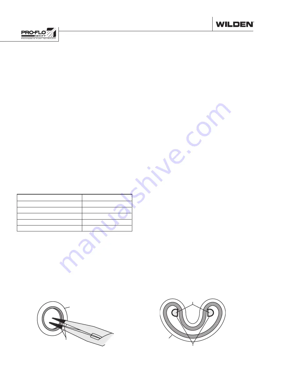
•   With a new seal in hand, place the two legs of the 

needle-nose pliers inside the seal ring. (See Figure A.)

•   Open the pliers as wide as the seal diameter will allow, 

then with two fingers pull down on the top portion of 
the seal to form a kidney shape. (See Figure B.)

•   Lightly clamp the pliers together to hold the seal into 

the kidney shape. Be sure to pull the seal into as tight 
of a kidney shape as possible, this will allow the seal to 
travel down the bushing bore easier.

•   With the seal clamped in the pliers, insert the seal into 

the bushing bore and position the bottom of the seal 
into the correct groove. Once the bottom of the seal is 
seated in the groove, release the clamp pressure on the 
pliers. This will allow the seal to partially snap back to 
its original shape.

•   After the pliers are removed, you will notice a slight 

bump in the seal shape. Before the seal can be properly 
resized, the bump in the seal should be removed as 
much as possible. This can be done with either the 
Phillips screwdriver or your finger. With either the side 
of the screwdriver or your finger, apply light pressure 
to the peak of the bump. This pressure will cause the 
bump to be almost completely eliminated.

•   Lubricate the edge of the shaft with NLGI grade 2 white 

EP bearing grease.

•   Slowly insert the center shaft with a rotating motion. 

This will complete the resizing of the seal.

•   Perform these steps for the remaining seals.

Figure A

SHAFT SEAL

TAPE

Figure B

SHAFT SEAL

TAPEAV

NEEDLE-NOSE 

PLIERS

PRO-FLO

®

 SHIFT MAXIMUM TORQUE

SPECIFICATIONS

Description of Part

Torque

Air Valve

11.3 N•m (100 in-lb)

Dial Set Screw

11.3 N•m (100 in-lb)

Outer Pistons, All diaphragms

47.1 N•m (30 ft-lb)

Top and Bottom Manifold

8.5 N•m (75 in-lb)

Liquid Chamber to Center Section

8.5 N•m (75 in-lb)

R E A S S E M B L Y   H I N T S   &   T I P S

Содержание Wilden PS220 Series

Страница 1: ...EOM Engineering Operation Maintenance wildenpump com Where Innovation Flows PS220 PS230 FIT Metal Pump...

Страница 2: ...5 PERFORMANCE PS220 PS230 Rubber Fitted 6 PS220 PS230TPE Fitted 6 PS220 PS230 Full Stroke PTFE Fitted 7 SECTION 6 SUGGESTED INSTALLATION OPERATION TROUBLESHOOTING 9 SECTION 7 DISASSEMBLY REASSEMBLY 12...

Страница 3: ...flammable fluids and whenever discharge of static electricity is a hazard CAUTION Do not exceed 8 6 bar 125 psig air supply pressure CAUTION The process fluid and cleaning fluids must be chemically co...

Страница 4: ...TE NOT ALL PUMP MODELS ARE AVAILABLE WITH ALL MATERIAL OPTIONS 0493 U L Approved Center Ported NPT Turbo drop in 1 Inlet facing air inlet 3 4 discharge facing exhaust 0494 U L Approved Center Ported N...

Страница 5: ...nd manifold of the pump These same hydraulic forces lift the discharge valve ball off its seat while the opposite discharge valve ball is forced onto its seat forcing fluid to flow through the pump di...

Страница 6: ...inch A 361 14 2 B 36 1 4 C 163 6 4 D 254 10 0 E 287 11 3 F 56 2 2 G 417 16 4 H 71 2 8 J 140 5 5 K 155 6 1 L 206 8 1 M 173 6 8 N 104 4 1 P 127 5 0 R 10 0 4 LW0364 REV A DIMENSIONS ITEM METRIC mm STAND...

Страница 7: ...NDARD inch A 373 14 7 B 69 2 7 C 195 7 6 D 287 11 3 E 340 13 4 F 343 13 5 G 71 2 8 H 417 16 4 J 71 2 8 K 140 5 5 L 188 7 4 M 206 8 1 N 173 6 8 P 104 4 1 R 127 5 0 S 10 0 4 T 203 8 0 DIN mm ANSI inch U...

Страница 8: ...and performance pumps should be specified so that daily operation parameters will fall in the center of the pump s performance curve Flow rates indicated on chart were determined by pumping water For...

Страница 9: ...le Iron 29 kg 64 lb 316 Stainless Steel 31 kg 68 lb Air Inlet 13 mm 1 2 Inlet 25 mm 1 Outlet 25 mm 1 Suction Lift 5 2 m Dry 17 0 9 0 m Wet 29 5 Disp Per Stroke1 0 30 L 0 08 gal Max Flow Rate 197 lpm 5...

Страница 10: ...ng at 305 m 1 000 above sea level This chart is meant to be a guide only There are many variables that can affect your pump s operating characteristics The number of intake and discharge elbows viscos...

Страница 11: ...lers can be used to further reduce sound levels but they usually reduce pump performance ELEVATION Selecting a site that is well within the pump s dynamic lift capability will assure that loss of prim...

Страница 12: ...to the pump therefore stopping output This shut off valve should be located far enough away from the pumping equipment such that it can be reached safely in an emergency situation NEEDLE VALVE AIR SH...

Страница 13: ...ake it possible to identify pumps that are poorly suited to their applications Pump will not run or runs slowly 1 Ensure that the air inlet pressure is at least 0 3 bar 5 psig above startup pressure a...

Страница 14: ...ing it upside down and allowing any fluid to flow into a suitable container Be aware of any hazardous effects of contact with your process fluid NOTE The model photographed is a metal PX200 25 mm 1 pu...

Страница 15: ...manifold Step 6 Remove the inlet valve balls seats and valve seat O rings from the liquid chamber and inlet manifold inspect for nicks gouges chemical attack or abrasive wear Step 7 Using a 13 mm 1 2...

Страница 16: ...cure shaft with soft jaws a vise fitted with plywoodorothersuitablematerial to ensure shaft is not nicked scratched or gouged Using an adjustable wrench removediaphragmassembly from shaft Inspect all...

Страница 17: ...ects of contact with your process fluid The Wilden Pro Flo SHIFT metal pumps utilize a revolutionary Pro Flo SHIFT air distribution system Proprietary composite seals reduce the coefficient of frictio...

Страница 18: ...y Step 6 Remove pilot spool sleeve retaining snap ring on both sides of center section with snap ring pliers Step 7 Remove pilot spool sleeve from center section Step 8 With O ring pick gently remove...

Страница 19: ...tep 2 Next install an optional single point exhaust gasket 02 2621 52 The single point air valve gasket can be purchased as a spare part or included with the purchase of a new Pro Flo SHIFT pump Step...

Страница 20: ...surface of the new seal With a new seal in hand place the two legs of the needle nose pliers inside the seal ring See Figure A Open the pliers as wide as the seal diameter will allow then with two fi...

Страница 21: ...N O T E S...

Страница 22: ...P L O D E D V I E W P A R T S L I S T I N G PS220 PS230 METAL E X P L O D E D V I E W WILDEN PUMP ENGINEERING LLC 20 WIL 11560 E 07 FULL STROKE PTFE FULL STROKE IPD STAINLESS STEEL FLANGED ALL CIRCLE...

Страница 23: ...5090 01 02 5090 02 02 5090 03 Inlet Manifold DIN Flange 1 02 5091 01 02 5091 02 02 5091 03 18 Discharge Manifold Side Ported 1 NPT 1 02 5035 01 02 5035 02 02 5035 03 Discharge Manifold Side Ported 1...

Страница 24: ...N 02 1010 86 N A N A N A N A N A N A N A FKM 02 1010 53 N A N A N A 02 1085 53 N A 02 1205 53 02 1372 53 EPDM 02 1010 54 N A N A N A 02 1085 54 N A 02 1205 54 02 1372 54 PTFE N A 02 1040 55 N A N A 0...

Страница 25: ...N O T E S...

Страница 26: ...N O T E S...

Страница 27: ...s for warranty consideration and must be accompanied by the appropriate MSDS for the product s involved A Return Goods Tag obtained from an authorized Wilden distributor must be included with the item...

Страница 28: ...nt without prior notice This is a non contractual document 11 2018 Authorized PSG Representative Copyright 2018 PSG ADoverCompany WIL 11560 E 07 REPLACES WIL 11560 E 07 PSG 22069 Van Buren St Grand Te...

Отзывы: