2 -Wire Intercom System
PRO
591/592 User Manual
3529,6,216(&85,7<352'8&76
5(9
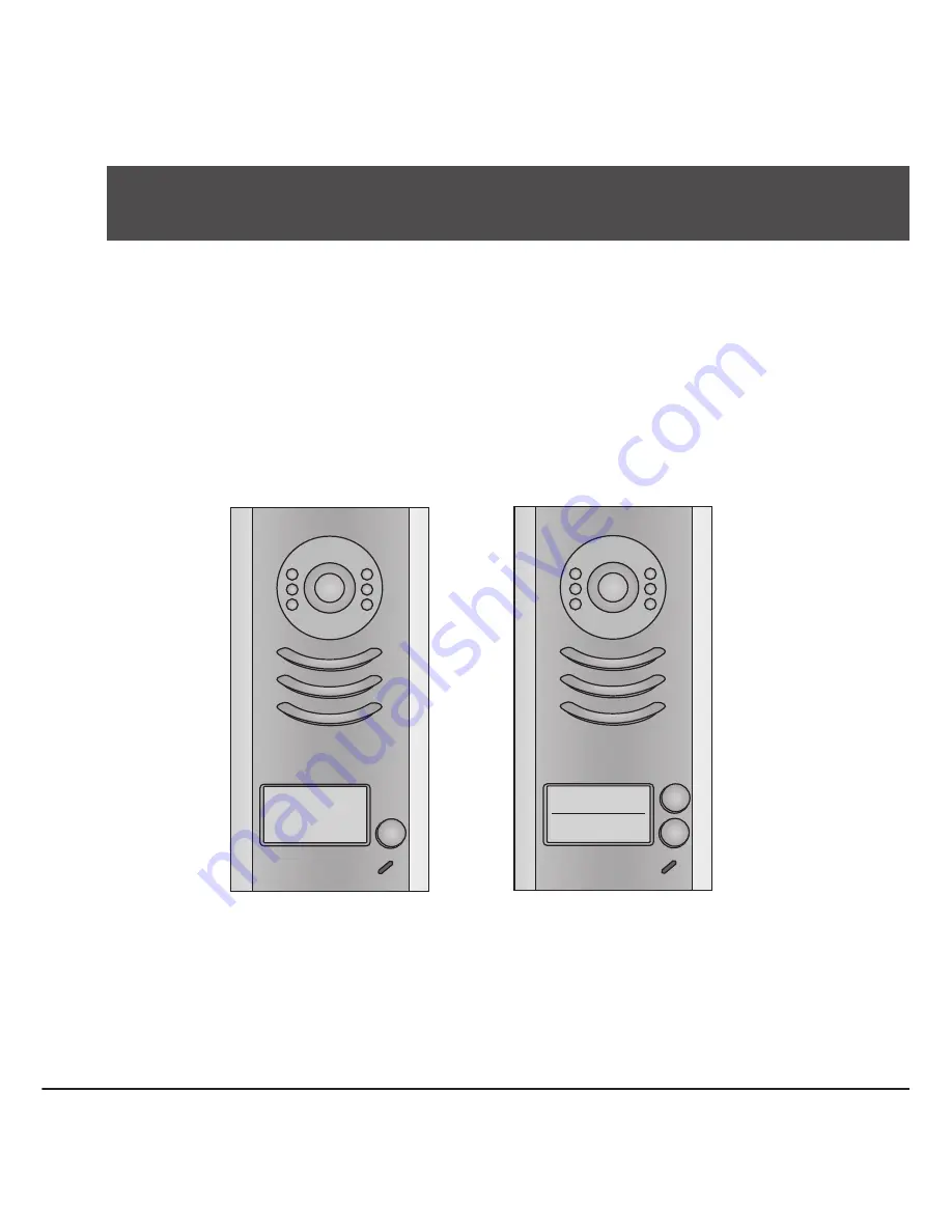
591
592
Страница 1: ...2 Wire Intercom System PRO591 592 User Manual 3529 6 21 6 85 7 352 8 76 5 9 PRO591 PRO592...
Страница 2: ...nection 4 5 2 Electric Lock Connection 5 5 2 1 Door Lock Controlled with Internal Power 5 5 2 2 Door Lock Controlled with Dry Contact 5 5 2 3 How to setup the unlock parameter in Monitor 6 5 3 Multi D...
Страница 3: ...ht View LED Speaker Nameplate Call Button Microphone 90 mm 176 mm 23 mm 2 Terminal Descriptions BUS PL S1 S2 S 1 2 ON 1 2 ON MIC adjustment Lock Control Jumper Doorstation Code DIP Main Connect Port 1...
Страница 4: ...S2 Lock power output to connect 2 locks S Lock power output connect to the power input of locks only when using the camera to power the locks if using the external power supply for the locks the S wi...
Страница 5: ...With Rainy Cover 160 165cm 1 2 1 2 3 4 4 3 Placing Name Label Move the plastic cover away to open the transparent name label cover insert a name paper then put the plastic cover back to the panel nam...
Страница 6: ...ng Camera Angle 5 1 Basic Connection use a screwdriver to loosen the screw and then adjust the angle of the camera then fix the screw 5 System Wiring and Connections AC monitor PRODPS PROPS4 1 2 ON L1...
Страница 7: ...Unlock Mode Parameter of Monitor must be set to 0 by default EB LOCK BUS PL S1 S2 S LOCK 2nd 1ST 2nd EB 1ST Jumper position in Connect two locks 1 2 EB LOCK BUS PL S1 S2 S Jumper position in Connect o...
Страница 8: ...n Code Number 0010 Remove all remote control 0011 Add remote control 8000 Set as master unit 0 8001 Set as slaver unit 1 8002 Set as slaver unit 2 8003 Set as slaver unit 3 8004 Set as guard unit 8005...
Страница 9: ...85 260VAC PRODPS PROS5 monitors 1 2 ON L1 L2 PL S1 S2 S 1 2 ON L1 L2 PL S1 S2 S 1 2 ON L1 L2 PL S1 S2 S 1 2 ON L1 L2 PL S1 S2 S 1 2 ON 1 2 ON 1 2 ON 1 2 ON 1 Camera ID 00 ID 10 ID 01 ID 11 2 Camera 3...
Страница 10: ...asic IN OUT Wiring Mode 5 4 Multi Monitors Connection ID 00 1 2 ON Code 0 DIP 6 off Code 14 DIP 6 off Code 15 DIP 6 on 1 2 3 4 5 6 ON 1 2 3 4 5 6 ON 1 2 3 4 5 6 ON monitor monitor monitor 85 260AC PRO...
Страница 11: ...D IN OUT 352 C 4 A B C D IN OUT 85 260AC PRODPS PROS5 1 2 3 4 5 6 ON 1 2 3 4 5 6 ON 1 2 3 4 5 6 ON 1 2 3 4 5 6 ON Code 15 DIP 6 on Code 13 DIP 6 on Code 3 DIP 6 on Code 1 DIP 6 on 1 2 3 4 5 6 ON 1 2...
Страница 12: ...Door Station ID 2 01 set to the third Door Station ID 3 11 set to the fourth Door Station 1 2 ON 1 2 ON 1 2 ON 1 2 ON There are 6 bit switches in total The DIP switches are used to configure the User...
Страница 13: ...1 2 3 4 5 6 ON Code 31 Code 10 Code 21 Note Monitors response button A must set the user code from 0 to 15 and button B set the user code from 16 to 31 A B A Bit 1 to Bit 5 are used to User Code sett...
Страница 14: ...0Vac input 24Vdc 3A output 10 DIN modules Connect with multi doorstations or multi monitors up to 2 or above 3526 24V Power supply 85 260Vac input 24Vdc 1A output for basic kit only 4 DIN modules Conn...
Страница 15: ...DFK When Monitor quantity 20 Cable Usage A B C Twisted cable 2x0 75 mm2 60 60 30 Twisted cable 2x1 mm2 80 80 40 When Monitor quantity 20 Cable Usage A B C Twisted cable 2x1 mm2 70 30 20 Twisted cable...
Страница 16: ...The design and specifications can be changed without notice to the user Right to interpret and copyright of this manual are preserved...