


Chapter 2 System Configuration
PA-3122 SERIES USER
’
S MANUAL
Page: 2-9
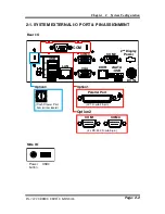
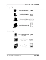
2-2-1. How to Set Jumpers
You can configure your board by setting the jumpers. A jumper consists of two or three
metal pins with a plastic base mounted on the card, and by using a small plastic
"
cap
"
,
also known as the jumper cap (with a metal contact inside), you are able to connect the
pins. So you can set-up your hardware configuration by
"
opening
"
or
"
closing
"
pins.
Jumpers can be combined into sets that called jumper blocks. When jumpers are all in
the block, you have to put them together to set up the hardware configuration. The
figure below shows what this looks like.
Jumpers & caps
If a jumper has three pins for example, labelled PIN1, PIN2, and PIN3. You can
connect PIN1 & PIN2 to create one setting and shorting. You can either connect PIN2
& PIN3 to create another setting. The same jumper diagrams are applied all through
this manual. The figure below shows what the manual diagrams look and what they
represent.
Содержание PA-3122
Страница 1: ...USER S MANUAL PA 3122 10 4 POS Terminal Powered by Intel Celeron J1900 Quad Core PA 3122 M1...
Страница 21: ...Chapter 2 System Configuration PA 3122 SERIES USER S MANUAL Page 2 10 Jumper diagrams Jumper settings...
Страница 101: ...Chapter 3 Software PA 3122 SERIES USER S MANUAL Page 3 42 e Example 3 PROMAG MSR PART NO HID mode...
Страница 165: ...Chapter 3 Software PA 3122 SERIES USER S MANUAL Page 3 106...
Страница 187: ...Chapter 4 System Assembly PA 3122 SERIES USER S MANUAL Page 4 4 With i Button 05 07 08 09 10 06 02 01 03 04...
Страница 189: ...Chapter 4 System Assembly PA 3122 SERIES USER S MANUAL Page 4 6...
Страница 190: ...Chapter 4 System Assembly PA 3122 SERIES USER S MANUAL Page 4 7 With MSR 05 07 08 06 02 01 03 04...
Страница 191: ...Chapter 4 System Assembly PA 3122 SERIES USER S MANUAL Page 4 8 With MSR 01 Without MSR 02...
Страница 193: ...Chapter 4 System Assembly PA 3122 SERIES USER S MANUAL Page 4 10...
Страница 194: ...Chapter 4 System Assembly PA 3122 SERIES USER S MANUAL Page 4 11 05 07 08 06 02 01 03 04 12 09 11 13 10 Back side...
Страница 195: ...Chapter 4 System Assembly PA 3122 SERIES USER S MANUAL Page 4 12...
Страница 198: ...Chapter 4 System Assembly PA 3122 SERIES USER S MANUAL Page 4 15 02 01 Push...
Страница 199: ...Chapter 4 System Assembly PA 3122 SERIES USER S MANUAL Page 4 16 Heatsink 05 02 01 03 04...
Страница 200: ...Chapter 4 System Assembly PA 3122 SERIES USER S MANUAL Page 4 17 Mainboard 02 05 07 08 06 01 03 04...
Страница 201: ...Chapter 4 System Assembly PA 3122 SERIES USER S MANUAL Page 4 18...
Страница 203: ...Chapter 4 System Assembly PA 3122 SERIES USER S MANUAL Page 4 20...
Страница 204: ...Chapter 4 System Assembly PA 3122 SERIES USER S MANUAL Page 4 21 3 Inch Printer Cover 05 07 08 06 02 01 03 04 09 10...
Страница 205: ...Chapter 4 System Assembly PA 3122 SERIES USER S MANUAL Page 4 22 2 Inch Printer 05 07 08 06 02 01 03 04 09 11 10...
Страница 206: ...Chapter 4 System Assembly PA 3122 SERIES USER S MANUAL Page 4 23 2 Inch Printer Cover 05 07 08 06 02 01 03 04 09 10...
Страница 207: ...Chapter 4 System Assembly PA 3122 SERIES USER S MANUAL Page 4 24 With Paper Holder 02 01 Without Paper Holder 03...
Страница 208: ...Chapter 4 System Assembly PA 3122 SERIES USER S MANUAL Page 4 25 EXPLODED DIAGRAM FOR MSR 02 01 03 04...
Страница 209: ...Chapter 4 System Assembly PA 3122 SERIES USER S MANUAL Page 4 26 EXPLODED DIAGRAM FOR VFD VFD Module 05 02 01 03 04...
Страница 210: ...Chapter 4 System Assembly PA 3122 SERIES USER S MANUAL Page 4 27 Without VFD Module 01...