background image


Read First: Safety Information 

To ensure that the tester is used safely, follow these instructions: 


Do not use the DMM if the tester or test leads appear damaged or if you suspect that the 

DMM is not operating properly. 


Disconnect the live test lead before disconnecting the common test lead. 


When using the test leads, keep your fingers behind the finger guards on the test leads. 


Do not apply more than 600V rms between a DMM terminal and earth ground.


Disconnect the test leads from the object circuit before measuring the voltage. The DMM 

enters scan mode automatically. Then connect the test leads to the voltage. Do not connect 

the test leads to the circuit first and then switch it on before the circuit is powered

If so, the 

DMM will go to the resistance measure function first when it’s powered, and it’s easy to be 

damaged or operated incorrectly when the power is suddenly switched on.   


Use caution when working with voltages above 60V dc or 30V AC rms. Such voltages pose a 

shock hazard. 


The user is cautioned that failure to use this equipment in accordance with the manufacturer’s 

instruction  may  be  detrimental  to  the  operation  of  this  equipment  and  may  impair  any 

Содержание MT-1503

Страница 1: ...MT 1503 SMART Multimeter Instruction Sheet ...

Страница 2: ...he object circuit before measuring the voltage The DMM enters scan mode automatically Then connect the test leads to the voltage Do not connect the test leads to the circuit first and then switch it on before the circuit is powered If so the DMM will go to the resistance measure function first when it s powered and it s easy to be damaged or operated incorrectly when the power is suddenly switched...

Страница 3: ...nce measure mode to measure it when the resistance in the input terminals is below 40Mohm Input DC voltage between 0 7V and 600V on the input terminals or between 0 12V and 600V or even AC voltage between 3V and 600V frequency between 40 Hz and 400Hz then the DMM enters the corresponding measure mode for DC voltage or AC voltage In DC and AC voltage modes the DMM has high input impedance 10MΩ If t...

Страница 4: ...tomatic Selection When the Volts DC is above 0 7V or 0 12V Volts AC is above 3Vrms the DMM enters volt measure mode automatically The LCD will indicate the voltage with DC or AC and its shown with figures in the corresponding units V or mV Change the test leads for the contacting point of the tested circuit if you want to test the DC voltage below 0 7V you can get the voltage of as low as 0 12V Wa...

Страница 5: ... to the meter or injury if the fuse blows never attempt an in circuit current measurement where the open circuit potential to earth is greater than 250V To avoid damage to the meter check the meter s fuses before proceeding Never place the probes in parallel with a circuit or component when the leads are plugged into the current terminals 2 Button Definition Due to the fact this meter only contain...

Страница 6: ...splay of reading To press the button the display value will be locked and kept unchanged To press the button again the locked status will be erased and enter the normal measurement status b In auto selection mode the button has no effect on them MAX MIN BUTTON a Press MAX MIN button to enter MAX mode it keeps the maximum measured value all along press it once more it then enters MIN mode and keeps...

Страница 7: ...ppens if SELECT button is pressed when SCAn appears in the LCD Continuously press this button DMM will exit the status of auto selection and then enter the specific measure mode DCV ACV OHM Diode Contynuity Capacity SCAN can be selected in turn DC and AC Voltage measurement a Connect the black test lead to COM socket and red test leads to the VΩHz socket b Press SELECT button to DCV or ACV positio...

Страница 8: ...in handing capacitors because they may have a charge on them of considerable power before discharging b Connect the black test lead to COM socket and red test leads to the VΩHz socket c Press SELECT button to nF position d If REL button is equipped press REL button you can use the relative function to eliminate the zero error If not equipped you will otherwise need to subtract the zero error when ...

Страница 9: ...D Auto Power OFF a If the buttons of the meter have no action within certain time the system will be power off automatically sleep mode It s 10 minutes to auto power off In auto power off status pressing the function key or enable the function switch the meter will Auto Power On Operation Mode b To press and hold any button to power on auto power off function will be disabled Maintenance Clean the...

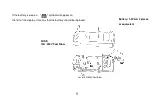
Страница 10: ... If the battery is weak a symbol will appear on the left of the display It means that the battery should be replaced Battery 1 5V AA 2 pieces or equivalent FUSE 10A 250V Fast Blow Fuse 10A 250V Fast Blow ...

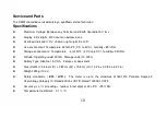
Страница 11: ...midity 85 RH Storage environment Temperature 4 to140 F 20 C to 60 C humidity 95 RH Altitude Operating under 2000m Storage under 10 000m Battery Type Alkaline 1 5V AA 2 pieces or equivalent Size HxWxL 3 36 cm D x 7 82 cm W x 15 8 cm H 1 32 in x 3 08 in x 6 22 in Weight 290g 10 oz Safety standards ETL LVD The meter is up to the standards of IEC1010 Pollution Degree 2 Overvoltage Category Ⅲ Rated 600...

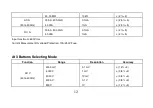
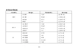
Страница 12: ...cy ACV 4 000V 40 00V 400 0V 500V 1 mV 10 mV 0 1 V 1 V 0 8 3 0 8 3 0 8 3 1 2 3 DC V 4 000 V 40 00 V 400 0 V 500 V 1 mV 10 mV 0 1 V 1 V 0 5 3 0 5 3 0 5 3 0 8 3 Ω 400 0 Ω 4 000 kΩ 40 00 kΩ 400 0 kΩ 4 000 MΩ 0 1 Ω 1 Ω 10 Ω 0 1 k Ω 1 kΩ 1 5 1 3 1 3 1 3 1 3 ...

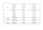
Страница 13: ...A 005 0 400 0mA 4 000A 0 1mA 1mA 2 5 2 5 Input maximum 600Vrms Current Measurement Overload Protection 10A 250V Fuse At 3 Buttons Selecting Mode Function Range Resolution Accuracy AC V 40 to 400Hz 400 0mV 4 000V 40 00V 400 0V 500V 0 1 mV 1 mV 10m V 0 1 V 1V 1 2 3 0 8 3 0 8 3 0 8 3 1 2 3 ...

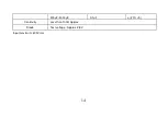
Страница 14: ... 0 5 3 0 5 3 0 5 3 0 5 3 0 8 3 Ω 400 0 Ω 4 000 kΩ 40 00 kΩ 400 0 kΩ 4 000 MΩ 40 00 MΩ 0 1 Ω 1 Ω 10 Ω 0 1 k Ω 1 kΩ 10 kΩ 1 5 1 3 1 3 1 3 1 3 2 3 AC A 40 to 400Hz 005 0 400 0mA 4 000A 0 1mA 1mA 2 5 5 2 5 5 DC A 005 0 400 0mA 4 000A 0 1mA 1mA 2 5 2 5 Capacity 40nF 40µF 10pF 3 5 ...

Страница 15: ...14 400µF 4000µF 0 1µF 20 5 Continuity Less than 100Ω Approx Diode Test voltage Approx 2 8V Input maximum 600Vrms ...

Страница 16: ...15 ...
Отзывы: