background image

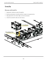
Fan Mount

Mounting Hole

S

yStem

 F

an

r

ePLACing


the

 s

ystem

 F

An

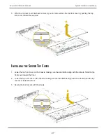
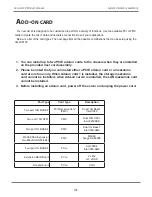
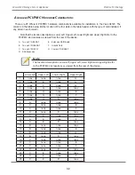
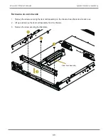
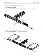
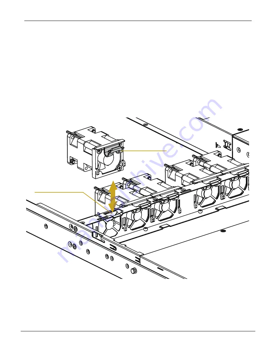
1.  Unplug the fan connecter and remove the failed fan.

2. 

Align the mounting holes on the fan bar with the fan mounts on the replacement fan.

3.  Gently place the fan on the fan bar. Make sure the fan is well seated.

4.  Connect the end of the fan cable to the fan connector.

39

System Hardware Assembly

Vess A6120 Product Manual 

Содержание Vess A Series

Страница 1: ...Vess A Series Storage Server Appliance Vess A6120 Product Manual Version 1 0 2016 PROMISE Technology Inc All Rights Reserved ...

Страница 2: ...including interference that may cause undesired operation Warning The electronic components within the Vess enclosure are sensitive to damage from Electro Static Discharge ESD Observe appropriate precautions at all times when handling the Vess or its subassemblies Warning Turn off the power and disconnect the power cord before servicing this device Warning Risk of Explosion if Battery is replaced ...

Страница 3: ...ossibility of physical injury and how to avoid them Caution A Caution informs you of possible equipment damage or loss of data and how to avoid them Important An Important message calls attention to an essential step or point required to complete a task including things often missed Note A Note provides helpful information such as hints or alternative ways of doing a task ...

Страница 4: ...12 Vess A6120 Packing List 12 Mounting Vess A6120 in a Rack 13 Installing Disk Drives 16 Drive carrier hardware 16 Remove Drive Security Cover 17 Management Connection 19 Management Path on site keyboard and monitor 19 Management Path network connection 20 Connecting the Power 21 Power On Vess A6120 system 21 Back Panel LEDs 21 Front Panel LEDs 23 Connect to iSCSI Storage Area Network SAN 24 ...

Страница 5: ...er Top Covers 26 Installing the Server Top Cover 27 Power Supply 29 Removing the Power Supply Unit 30 Add on card 31 Available PCI PMC Hardware Combinations 32 Installing an add on card 33 LAN Mezzanine Card 36 Installing a LAN Mezzanine Card 37 System Fan 39 Replacing the System Fan 39 ...

Страница 6: ...g Your Logical Drives 50 Automatic Configuration 51 Express Configuration 52 Advanced Configuration 54 Subsystem Management 57 Background Activities 58 View Current Background Activities 58 View Background Activities Parameters settings 58 Manage Background Activities Settings 59 Rebuild Settings 60 Background Synchronization 60 Logical Drive Initialization 61 Redundancy Check 62 PDM 63 Transition...

Страница 7: ...ipt 73 Exporting a Configuration Script 74 Saving a Service Report 75 Email Service 77 Stop Email Service 77 Restarting Email Service 77 Email Settings 78 Sending A Test Email Message 78 Performance Monitoring 79 Controllers 81 View Controller Information 81 Viewing Controller Statistics 83 Controller Settings 84 Enclosures 85 Enclosure Information 85 Enclosure temperature sensor settings 86 Buzze...

Страница 8: ... CLU 104 Viewing Controller Information CLU 104 Clearing Statistics 104 Making Controller Settings CLU 105 Managing the Enclosure CLU 107 Viewing the Enclosures Summary CLU 107 Viewing Enclosure Information CLU 108 Adjustable items 108 Making Enclosure Settings CLU 108 Viewing Power Supply Status CLU 109 To view the status of the power supplies 109 Viewing Cooling Unit Status CLU 109 Viewing Tempe...

Страница 9: ... Settings CLU 131 Running Spare Check CLU 131 Deleting a Spare Drive CLU 132 Managing Logical Drives CLU 133 Creating a Logical Drive CLU 133 Deleting a Logical Drive CLU 135 Viewing Logical Drive Information CLU 136 Viewing Logical Drive Statistics CLU 136 Viewing the Logical Drive Check Table CLU 137 Making Logical Drive Settings CLU 137 Initializing a Logical Drive CLU 138 Running Redundancy Ch...

Страница 10: ... of Trap Sinks 153 Adding a Trap Sink 153 Deleting a Trap Sink 154 Clearing Statistics CLU 154 Restoring Factory Defaults CLU 155 Buzzer 156 Making Buzzer Settings 156 Silencing the Buzzer 156 Managing with the CLI 157 Opening the CLI on Windows 157 Table of Supported Commands 158 Table of Supported Commands Continued 159 Notes and Conventions 160 ...

Страница 11: ...onfig 172 ctrl 173 event 178 export 180 factorydefaults 181 import 183 init 184 logdrv 186 logout 187 menu 188 mp 188 net 189 password 190 pdm 190 phydrv 192 rc 195 rb 196 sc 197 spare 198 swmgt 200 stats 203 subsys 204 sync 206 transit 207 user 209 help 210 210 ...

Страница 12: ...e alarm buzzer 224 Reinstalling the Operating System 225 Reintsall Windows 226 Contacting Technical Support 227 Limited Warranty 231 Disclaimer of other warranties 232 Your Responsibilities 233 Returning the Product For Repair 233 Update Installation Requirements 236 USB Flash Drive 236 Operation Systems 236 Download Driver Package 236 Update Install the Driver 237 Uninstall Driver 241 How to chec...

Страница 13: ...ain variations for the Vess A6120 series to be deployed based on the needs of your project Vess Orange A6120 AS is equipped with 2 Intel Xeon E5 2620 v4 CPUs plus 16GB RAM expandable to 128GB It is suitable for analyzing huge amounts of video data intelligent video analytics Vess Black A6120 MS is equipped with 1 Intel Xeon E5 2620 v4 CPU plus 8GB RAM expandable to 128GB It is the best choice for ...

Страница 14: ...System Hardware Overview System Components 2 Vess A6000 Series NVR Server Promise Technology ...

Страница 15: ...Internal Features Refer to the illustration below and table on the following page to locate internal hardware components of the server Internal Hardware 3 Introduction Vess A6120 Product Manual ...

Страница 16: ...SU2 6 Power Supply Unit PSU1 7 System Fan FAN1 8 System Fan FAN2 9 System Fan FAN3 10 System Fan FAN4 11 System Fan FAN5 12 HDD Backplane Board BPB 13 2 5 HDD Carrier HDD0 14 2 5 HDD Carrier HDD1 15 Front Panel Board FPB 16 4 x 3 5 Hot Swap HDD Trays HDD0 HDD3 Supports Low profile and FHHL Full High Half Length PCIe cards Supports 1GbE x 2 10GbE x2 or SFP mezzaine cards Supports 7mm 2 5 inch HDD o...

Страница 17: ...gical drive provides maximum performance in a compact external enclosure Also on the front panel are two USB 2 0 ports LED indicators power button UID button and VGA port See Front Panel Controls and LED indicators on page 7 for details about LED indicators and controls on the front panel No Description 1 4 x 3 5 Hot Swap HDD Trays HDD0 HDD3 2 2 x USB 2 0 Ports 3 Control Panel Buttons and LEDs 4 V...

Страница 18: ...ing 2 I O ports including two USB 3 0 ports and one 1000BASE T port for BNC use only 3 1 x PCI Express Slot 1 on the riser card assembly Supports Low profile and FHHL Full High Half Length PCIe cards 4 1 x LAN Mezzanine Card Slot Support for 1GbE x 2 10GbE x2 or SFP x2 5 1 x PCI Express Slot 2 on the riser card assembly Supports Low profile and FHHL Full High Half Length PCIe cards Rear Panel Hard...

Страница 19: ...ooling unit module Use the tubular key shipped with the unit to lock or unlock this cover to access the six hard drive carrier trays and removable cooling unit in front The left panel contains the power button various LEDs USB ports and the tubular lock Note that top illustration below represents the Vess A6120 front panel LEDs and controls with the bezel cover removed Front Panel LEDs with bezel ...

Страница 20: ... System is normally operating RAID Status LED Status Description Blinking Green At lease one of the HDDs is accessing data Solid Green At lease one of the HDDs is connected Solid Red One or more HDD has failed Off No HDD is present 8 Vess A6000 Series NVR Server Promise Technology ...

Страница 21: ...button to toggle the front panel UID LED and the baseboard UID LED on and off You are able to locate the server you re working on from behind a rack of servers Power Button Press the power switch button to toggle the system power on and standby sleep modes To remove all power from the system completely disconnect the power cord from the server 9 Introduction Vess A6120 Product Manual ...

Страница 22: ...pe Size 64K 128K 256K 512K and 1MB Max LUNs 256 logical drives per controller Networking 1GbE x 4 1GbE x 2 1GbE x 2 Power Supply Dual 650W Platinum Dimension 710mm x 430mm x 43 5 mm System Cooling 5 swappable fans Preloaded OS WS2012 R2 WS2012 R2 Windows 10 Enterprise Management Tools GUI SNMP via Ethernet CLI CLU via Ethernet or Graphics OPAS Service via USB SDK or API for integration Safety Cert...

Страница 23: ...on of the equipment in a rack should be such that the amount of air flow required for safe operation of the equipment is not compromised Mechanical Loading Mounting of the equipment in the rack should be such that a hazardous condition is not achieved due to uneven mechanical loading Circuit Overloading Consideration should be given to the connection of the equipment to the supply circuit and the ...

Страница 24: ...ess A6120 box contains the following items Vess A6120 unit Front bezel secure cover 1 5m 4 9 ft Power cord Screws for disk drives 20 pieces for 4 bays Sliding rail assembly for rack mounting 12 Vess A6000 Series NVR Server Promise Technology ...

Страница 25: ...erefore consideration should be given to installing the equipment in an environment compatible with the maximum ambient temperature Tma specified by the manufacturer Reduced Air Flow Installation of the equipment in a rack should be such that the amount of air flow required for safe operation of the equipment is not compromised Mechanical Loading Mounting of the equipment in the rack should be suc...

Страница 26: ...ology 1 For both sliding rail assemblies release and detach the inner member from the slide 2 Attach the inner member of the sliding rail assembly to each side of the Vess A6120 Follow these steps to install the mounting rails in an equipment rack ...

Страница 27: ...15 Introduction Vess A6120 Product Manual 3 Fix the outer member of the rail assembly to the rack frame 4 Carefully insert the Vess A6120 to complete the installation ...

Страница 28: ...e carrier hardware Installing Disk Drives The Vess A6120 system supports SATA hard disks 3 5 inch hard disk drives For a list of supported physical drives download the latest compatibility list from the PROMISE support website 16 Vess A6000 Series NVR Server Promise Technology ...

Страница 29: ...traight back to remove Be careful not to drop the cover Follow these steps to install the hard disks 1 Press the drive carrier release button The handle springs open 2 Grasp the handle and gently pull the empty drive carrier out of the enclosure Cautions Swing open the drive carrier handle before you insert the drive carrier into the enclosure To avoid hand contact with an electrical hazard remove...

Страница 30: ... for 2 5 drives 3 Insert the screws through the proper holes in the carrier and into the drive or adapter Install four screws per drive Snug each screw Be careful not to over tighten 4 With the drive carrier handle in open position gently slide the drive carrier into the enclosure Important Press the release button to push the drive carrier into position Proper drive installation ensures adequate ...

Страница 31: ... and manage the initial setup configuration via direct connection to the device using the Command Line Interface This Quick Start Guide describes only the second option connecting to the device with a monitor and keyboard Management Path on site keyboard and monitor Use a USB keyboard and a VGA monitor to establish a direct out of band connection to the management software The VGA and USB ports ar...

Страница 32: ...on 2 Attach one end of an Ethernet cable to one of the ports on the same network switch or subnet used for system administration Attach the other end of the Ethernet cable to one of the 1000BASE T ports on the back of the Vess A6120 If you have multiple Vess A6120 systems Host PCs or Servers repeat steps 1 and 2 as required 3 Follow the instructions for connecting to and configuring the basic sett...

Страница 33: ...y and connect the PSU to a suitable power source Power On Vess A6120 system With the power supplies connected the system can now be powered on To power on the Vess A6120 system press the Power button on the front panel Observe the LEDs on the front panel and on the back panel to make certain the boot up proceeds smoothly and the system is connected to the network Back Panel LEDs 21 Introduction Ve...

Страница 34: ...ort Speed LED Description Link Activity This is lit YELLOW when a physical link is established it blinks YELLOW when there is activity on the port Port Speed GREEN indicates 1000 Mbps YELLOW indicates 100 Mbps Unlit indicates 10 Mbps or no link 22 Vess A6000 Series NVR Server Promise Technology ...

Страница 35: ...y it remains unlit Network Link Activity One LED for each 1000BASE T LAN port These are lit GREEN to indicate a valid link A blinking GREEN LED indicates activity on the port RAID Status This is lit GREEN when the RAID status is healthy It will be unlit if there is a problem with the RAID UID This will be lit BLUE when the system identification feature is active Otherwise is re mains unlit Front P...

Страница 36: ...se com support This arrangement requires A GbE network interface card NIC or iSCSI HBA NIC in the host PC or server A GbE network switch A standard network switch Note To expand physical capacity available for the Vess A6120 use the onboard iSCSI ports to connect to Vess R2000 Series storage enclosures and each Vess R2000 can also be connected to Vess J2000 Series JBOD expansion units 24 Vess A600...

Страница 37: ... the AC outlet and then from the server The power LED turns off 2 Ensure you have a clean and stable working environment Avoid dust and dirt because contaminants may cause malfunctions 3 Ground yourself properly before touching any system component A discharge of static electricity may damage components Wear a grounded wrist strap if available WARNING The server is not completely powered down when...

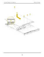
Страница 38: ...rd the rear of the chassis to remove the cover from the locked position Lift up and remove the top rear cover WARNING 1 Before removing the top cover power off the server and unplug the power cord 2 The system must be operated with the chassis top cover installed to ensure proper cooling 26 Vess A6120 Storage Server Appliance Promise Technology ...

Страница 39: ...1 Lower the top front cover on the chassis making sure the side latches align with the cutouts Slide the top front cover toward the front 2 Lower the top rear cover on the chassis making sure the side latches align with the cutouts Slide the top rear cover toward the front 3 Secure the both covers with the screws 27 System Hardware Assembly Vess A6120 Product Manual ...

Страница 40: ...28 Vess A6120 Storage Server Appliance Promise Technology ...

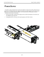
Страница 41: ...r supply purely as a redundant load sharing backup It can be removed without affecting system operation Installing and Removing the Power Supply 1 Align the power supply unit with the power supply slot Ensure that the LED appears on the left when you are installing the power supply unit 2 Carefully slide the PSU all the way into the power supply bay until it clicks into place 29 System Hardware As...

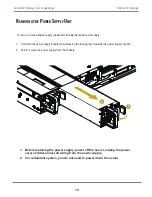
Страница 42: ...ressing the locking lever towards the power supply handle 2 Pull to remove the power supply from the chassis 1 Before replacing the power supply power off the server unplug the power cord and disconnect all wiring from the power supply 2 In a redundant system you do not need to power down the server 30 Vess A6120 Storage Server Appliance Promise Technology ...

Страница 43: ...AM2 M3008 SAS Expansion Two Mini SAS SFF 8643 PMC M3008 Avago SAS3008 Four port 1G BASE T PCIe AU 350X4 Intel I350 AM4 Extension RAID Board PCIe 2 x M 2 or 2 x SSD Graphics card PCIe VGA Add on card 1 You can install up to two PCIE add on cards to the chassis when they are installed on the provided riser card assembly 2 Please be noted that you can install either a PCIE add on card or a mezzanine ...

Страница 44: ...I PMC hardware combinations available for installation in the Vess A6120 The columns in the table below list the location of the four slots in the table header with the type of card installed if any listed in each column Note that the location descriptions Lower Left Upper Left Lower Right and Upper Right refer to the PCI PMC slot locations as viewed from the rear of the device A Two port 1G BASE ...

Страница 45: ... Remove the screws securing the riser card assembly on the chassis Keep this screw for later use 2 Lift up and remove the riser card assembly from the chassis 3 Remove the screw securing the filler plate 33 System Hardware Assembly Vess A6120 Product Manual ...

Страница 46: ...plate out sideways 6 Install an add on card into the retainer plate and into the connector on the riser card assembly 7 Secure the card to the assembly with a screw 8 Place the assembly back into the chassis and secure it with screws 34 Vess A6120 Storage Server Appliance Promise Technology ...

Страница 47: ...8 8 8 35 System Hardware Assembly Vess A6120 Product Manual ...

Страница 48: ...anine Card If you need to remove the blanking plate please remove the screws that secure the blanking plate on the chassis Keep the screws for later use The pre installed blanking plate is also the RJ 45 plug release module 36 Vess A6120 Storage Server Appliance Promise Technology ...

Страница 49: ...onjunction with a matching I O module For 10G BASE T mezzanine card you need to install the RJ 45 plug release module instead of a regular I O module 1 Install the four standoffs into the motherboard around the mezzanine card slot Hand tighten the standoffs 2 Gently insert the mezzanine card into the mezzanine card slot on the motherboard 37 System Hardware Assembly Vess A6120 Product Manual ...

Страница 50: ...rd standoffs 4 Tighten the screws to secure the matching I O module to the chassis Install the RJ 45 plug release module instead for the M540 mezzanine card 5 If you use the RJ 45 plug release module simply press it to release plugs 38 Vess A6120 Storage Server Appliance Promise Technology ...

Страница 51: ...nd remove the failed fan 2 Align the mounting holes on the fan bar with the fan mounts on the replacement fan 3 Gently place the fan on the fan bar Make sure the fan is well seated 4 Connect the end of the fan cable to the fan connector 39 System Hardware Assembly Vess A6120 Product Manual ...

Страница 52: ...in at the Enclosure At the Vess enclosure to log into WebPAM PROe do one of the following actions Double click the WebPAM PROe desktop icon Choose WebPAM PROe in the Windows Programs menu Follow the steps under Logging in over the Network on page 41 Note The default IP settings for the Gigabit Ethernet ports are Port 1 192 168 0 1 Port 2 192 168 1 1 IP settings for the ports are controlled by the ...

Страница 53: ... If you chose External SSL Security during installation use the Secure Connection Otherwise use the Regular Connection Regular Connection WebPAM PROe uses an HTTP connection http Enter the Subsystem IP address 192 168 0 1 Enter the Port number 8090 Together your entry looks like this http 192 168 0 1 8090 Important For Vess A Series running Windows OS it is necessary to disable the Windows Firewal...

Страница 54: ...ter the Port number 8443 Together your entry looks like this https 192 168 0 1 8443 Note You can enter the Host PC s network name in place of the IP address If you are logging in at the Host PC you can enter local Host in place of the IP address Whether you select a regular or a secure connection your login to WebPAM PROe and your user password are always secure ...

Страница 55: ...hen the opening screen appears 1 Type administrator in the User Name field 2 Type password in the Password field 3 Click the Login button The User Name and Password are case sensitive See Figure 1 The WebPAM PROe login screen After logging in the Quick Links menu appears ...

Страница 56: ... the administrator s Home page for WebPAM PROe Here you will find links to menus to view setting and manage logical drives physical drives and disk arrays Also links to view network settings and event logs as well as the background activities management menu Quick Links menu User s Home page ...

Страница 57: ...e Interface WebPAM PROe is browser based RAID management software with a graphic user interface Basic user interface components and functions include WebPAM PROe interface Subsystem home page There are four major parts to the WebPAM PROe interface Header Tree View Event Frame ...

Страница 58: ... navigate around all components of the Vess enclosure software management RAID controller enclosure physical drives disk arrays logical drives and spare drives The figure below shows the components of Tree View WebPAM PROe Tree View The Administrative Tools section is different for the Administrator and Super Users than for other users The remainder of the Tree is the same for all users Logged in ...

Страница 59: ...cess menus to control specific actions and processes Click the Help link to the right of the tabs in Management View to access online help for the function currently displayed Choosing a Display Language WebPAM PROe displays in the following languages English French German Italian Japanese Korean Simplified Chinese Traditional Chinese Spanish Russian Portuguese Turkish Arabic To change the display...

Страница 60: ...c type of event Severity See below Information Information only no action is required Warning User can decide whether or not action is required Minor Action is needed but the condition is not serious at this time Major Action is needed now Critical Action is needed now and the implications of the condition are serious Fatal Non Recoverable error or failure has occurred Time Time and date of the oc...

Страница 61: ...ut of WebPAM PROe There are two ways to log out of WebPAM PROe Close your browser window Click Logout in the WebPAM PROe Header Clicking Logout brings you back to the Login Screen After logging out you must enter your user name and password in order to log in again ...

Страница 62: ...al drive automatically Also makes a hot spare drive for all RAID levels except RAID 0 if at least four unconfigured physical drives are available Express Configuration You choose the parameters for a new disk array by specifying the characteristics you want You can create multiple logical drives at the same time however they will all be identical You can choose to make a hot spare drive for all RA...

Страница 63: ...gical drive s their RAID level capacity and stripe size Spare Drives The physical drive slot number of the dedicated hot spare assigned to this disk array A hot spare drive is created for all RAID levels except RAID 0 when five or more unconfigured physical drives are available Automatic Disk Array Configuration menu If you accept these parameters click the Submit button The new disk array appears...

Страница 64: ...will remain available if a physical drive fails Capacity The greatest possible amount of data capacity Performance The highest possible read write speed Spare Drive A hot spare drive is created when you choose Redundancy Spare Drive and five or more unconfigured physical drives are available 2 In the Number of Logical Drives field enter the number of logical drives you want to make from this disk ...

Страница 65: ...ves in the disk array their slot numbers configurable capacity and the number of logical drives to be created Logical Drives The slot number of the logical drive s their RAID level capacity and stripe size Spare Drives The physical drive slot number of the dedicated hot spare assigned to this disk array all RAID levels except RAID 0 If you accept these parameters proceed to the next step If you do...

Страница 66: ...name for the disk array in the field provided Maximum of 32 characters letters numbers space between characters and underline Uncheck the boxes if you want to disable Media Patrol or PDM PROMISE recommends leaving these features enabled Highlight physical drives you want in the disk array from the Available list and press the button to move them to the Selected list You can also double click them ...

Страница 67: ...a RAID level for the logical drive from the dropdown menu The choice of RAID levels depends the number of physical drives you selected RAID 30 and 50 only Specify the number of axles for your array Specify a Capacity and the unit of measure B KB MB GB TB This value will be the data capacity of the first logical drive in your new disk array If you specify less than disk array s maximum capacity the...

Страница 68: ... Read Ahead and No Cache are available Write cache Policy Write Back is the default Write Back and Write Through Thru are available 2 Click the Update button A new logical drive is displayed under New Logical Drives If there is free capacity remaining you can specify another logical drive now or wait until later 3 When you are done specifying logical drives click the Next button Step 3 Summary The...

Страница 69: ...or warnings and enable disable warning buzzer Disk Arrays manage disk arrays Spare Drives manage spare drives Logical Drives Summary read only logical drive information display Click on the subsystem IP address and model name listed under the Subsystems top level menu icon in Tree View In the Information tab the following information for the subsystem appears Alias Vendor Model Serial Number World...

Страница 70: ...activity affects I O performance View Current Background Activities To view current background activities 1 Click the Subsystem icon of the subsystem on which you want to view Background Activities 2 In the Subsystem menu click the Background Activities tab Background Activities currently running are displayed in the top portion of the menu You can also view the current Background Activities param...

Страница 71: ...ctivities tab and the Scheduler tab and select the Settings option The following settings can be configured Rebuild Rate High Medium Low Background Synchronization Rate High Medium Low Logical Drive Initialization Rate High Medium Low Redundancy Check Rate High Medium Low Migration Rate High Medium Low PDM Rate High Medium Low Transition Rate High Medium Low Reassigned Block Threshold Error Block ...

Страница 72: ...one physical drive When a physical drive in a disk array fails and a spare drive of adequate capacity is available the disk array begins to rebuild automatically using the spare drive If there is no spare drive of adequate capacity but the Auto Rebuild function is ENABLED the disk array begins to rebuild automatically as soon as you remove the failed physical drive and install an unconfigured phys...

Страница 73: ...le it is initiating Initialization is normally done to logical drives after they are created from a disk array Initialization sets all data bits in the logical drive to zero The action is useful because there may be residual data on the logical drives left behind from earlier configurations For this reason Initialization is recommended whenever you create a logical drive Logical Drive Initializati...

Страница 74: ...set up a Redundancy Check Schedule To set up a schedule click the menu expander to the right of the Scheduler tab and select Redundancy Check Schedule Redundancy Check Rate To change Redundancy Check Rate setting the in Background Activities Settings menu 1 Click the Redundancy Check Rate drop down menu and choose a rate Low Fewer system resources to Redundancy Check more to data read write operat...

Страница 75: ... More system resources to PDM fewer to data read write operations 2 Highlight the current values in the block threshold fields and input new values Reassigned Block Threshold range is 1 to 512 blocks Error Block Threshold range is 1 to 2048 blocks 3 Click the Submit button Transition Transition is the process of replacing a revertible spare drive that is currently part of a disk array with an unco...

Страница 76: ... enable Media Patrol click on the Subsystem in Tree View then click on the Background Activities menu tab Click to check the Enable Media Patrol option Notice also that the Auto Rebuild option is here as well If you want to automatically begin rebuilding a logical drive as soon as a faulty drive is replaced make sure this option is enabled To begin Media Patrol manually click on the menu expander ...

Страница 77: ...ick on the Scheduler menu expander to the right of the Scheduler tab Scroll down to the schedule option you want to view that menu Schedule options are Add Media Patrol Schedule Add Redundancy Check Schedule Add Spare Check Schedule and Delete Schedule View or modify an existing activity schedule To view existing schedules including the recurrence start time and status of existing schedules click ...

Страница 78: ...ing subsystems To view save or clear subsystem event logs click on the subsystem in Tree View then click on the Event menu expander Choose to display Runtime Events or NVRAM Events Event logs can be saved as a simple text file by clicking the Save button in either menu To clear the log and start fresh click the Clear Event Log button ...

Страница 79: ...he Restore Factory Defaults link to reveal a new menu 3 Check mark the option boxes for the settings you want to return to the factory default values Default Settings options include 4 Click the Submit button to return the selected settings to default values To deselect all options and start over click the Reset button Clear Statistics To clear all subsystem statistics for controllers ports physic...

Страница 80: ...iew Making User Settings To change settings of other users 1 Log into WebPAM PROe as the Administrator or a Super User 2 Click the Administrative Tools icon 3 Click the User Management icon 4 Click the Information tab 5 In the list of users click the link of the user whose settings you want to change The Settings screen for the chosen user displays 6 Enter or change the settings for this user Enab...

Страница 81: ...name or mail address 6 Click the Submit button Changing Your Own Password To set or change your own password 1 Log into WebPAM PROe under your own user name 2 Click the Administrative Tools icon 3 Click the User Management icon 4 Click the Password tab in Management View 5 Enter the current password in the Old Password field 6 If you do not have a password leave this field blank 7 Enter the new pa...

Страница 82: ... for this user in the New Password and Retype Password fields A password is optional If you do not assign password tell this user to leave the password field blank when he she logs into to WebPAM PROe 7 Check the Enabled box to enable this user on this subsystem 8 Enter a display name in the Display Name field A display name is optional but recommended 9 Choose a privilege level from the Privilege...

Страница 83: ...ives and the controller Super Allows the user full access to all functions including create and delete users and changing the settings of other users and delete disk arrays and logical drives The default administrator account is a Super User Deleting a User There is always at least one Super User account You cannot delete the user account you used to log in To delete a user 1 Log into WebPAM PROe ...

Страница 84: ...e Management The Software Management menu is used to manage settings for Email SNMP settings and Web services The Email function is used for sending notifications of events The Web service is used for remote network connection to the WebPAM PROe management interface This is also where you can export and import configuration script files and user database files If the port is enabled disabled If th...

Страница 85: ...one Vess subsystem export it and then import it to automatically configure your other Vess subsystems To import a configuration script 1 Click the Administrative Tools icon 2 Click the Software Management icon 3 Click the Import tab in the Service Management menu 4 Choose Configuration Script from the Type drop down menu 5 Click the Choose File button and select the configuration script on the Hos...

Страница 86: ... 1 Click the Administrative Tools icon 2 Click the Software Management icon 3 Click the Export tab in the Service Management menu 4 Choose Configuration Script from the Type drop down menu 5 Click the Export button 6 Select a location on the Host PC for the downloaded file and save the file The file is saved to your PC as Configscript txt Cautions Do NOT attempt to write or modify a configuration ...

Страница 87: ...IP address and device name in Tree View to open the Subsystem Information display 2 Click the Save button in the Save System Service Report row of the information display Information for the report is gathered and compiled This action takes up to a few minutes depending on the size of your RAID system 3 Determine where you want to store the file on the Host PC then click the Save button in the pop...

Страница 88: ...ent Info Runtime LogDrive Info Basic logical drive information LogDrive Dump Info Diagnostic information Logical Drive Verbose Info Full logical drive information Network Info Virtual port Phydriv Info Basic physical drive information Phydriv Verbose Info Full physical drive SWMGT Info Software management Service Setting Email Service Setting Webserver Spare Info Basic spare drive information Spar...

Страница 89: ...he Stop button under Service Status Email 5 Click the Confirm button To start the Email service after stopping it 1 Click the Administrative Tools icon 2 Click the Software Management icon 3 Click on Email in the Service List of the Service Management menu 4 Click the Start button under Service Status Email 5 Click the Confirm button Restarting Email Service To restart the Email service 1 Click th...

Страница 90: ...ption enables authentication The No option disables SMTP Authentication under Email Server Settings Username Required if SMTP authentication is enabled SMTP Authentication Password Required if SMTP authentication is enabled Under Email Content Customization Email Sender From Address The sender s name shown on notification messages Email Subject The subject line of the notification message 5 Click ...

Страница 91: ...itoring icon 3 Click the Information tab for aggregated statistics or choose the Read Write tab to view specific Read and Write performances separately 4 Under Logical Drive choose the metric you want to see from the Measurement drop down menu 5 Check the boxes for the logical drives you want to see Total of all logical drives Up to 4 devices Information Bandwidth in MB s Cache usage by Dirty cach...

Страница 92: ...splay it does not accumulate information and there is no clear or save function To save performance statistics for analysis or troubleshooting save a Service Report See Saving a Service Report Information Bandwidth in MB s Maximum latency in ms Average latency in ms Minimum latency in ms I Os per second Read Write Read bandwidth Write bandwidth Maximum Read latency in ms Maximum Write latency in m...

Страница 93: ...ange controller settings See the following sections View Controller Information Viewing Controller Statistics Controller Settings View Controller Information To view controller information 1 Click the Controllers icon 2 Click the specific Controller icon of the controller for which you want to view information 3 The Information tab will present basic controller information ...

Страница 94: ...ision WWN Install Package Version Install Package Build Date Memory Type Memory Size Flash Type Flash Size Preferred Cache Line Size Cache Line Size Coercion Enabled Disabled Coercion Method SMART Log Enabled Disabled SMART Polling Interval Write Back Cache Flush Interval Enclosure Polling interval Host Cache Flushing Enabled Disabled Forced Read Ahead Enabled Disabled Spin Down Type HDD Power Lev...

Страница 95: ...s 3 At the top of the Information display menu between the Information and Settings tabs click on the menu expander to reveal the Statistics link Reveal Statistics link Controller statistics include Data Transferred Read Data Transferred Errors Read Errors I O Requests Read IO Requests Statistics Start Time Write Data Transferred Non Read Write Errors Write Errors Non Read Write Requests Write I O...

Страница 96: ...terval Enter a value into the field 1 to 12 seconds HDD Power Saving Choose time periods from the drop down menus After an HDD has been idle for the set period of time Power Saving Idle Time Parks the read write heads Power Saving Standby Time Lowers disk rotation speed Power Saving Stopped Time Spins down the disk stops rotation Host Cache Flushing Check the box to enable or uncheck to disable Fo...

Страница 97: ...closure temperature sensor settings Buzzer Settings Physical Drives Enclosure Information The Enclosure Information read only display menu provides key real time information about current hardware status of the enclosure Click on the expanders buttons to reveal current conditions and status of the enclosure power supplies fans blowers temperature sensors and voltage sensors Move the cursor over th...

Страница 98: ... Threshold 90 95 C If the enclosure temperature reaches this threshold a warning message is sent and an event is recorded in the event log Controller Critical Temperature Threshold 100 105 C If the enclosure temperature reaches this threshold a warning message is sent an event recorded is recorded in the event log Buzzer Settings The audible enclosure alarm buzzer can be enabled or disabled To ena...

Страница 99: ...es To see the Physical Drives List expand the individual Enclosure icon in Tree View to see the Physical Drives icon for the enclosure To display the information for any populated slot you can expand the Physical Drives icon in Tree View to reveal links to each slot or click on the slot in the Physical Drives List or click on the populated slot in the virtual enclosure displayed in the menu View i...

Страница 100: ...ock Size Bytes Operational Status Configuration Status Model Drive Interface Serial Number Firmware Version Protocol Version Visible To Controller Write Cache Enabled Disabled Read Look Ahead Cache Enabled Disabled SMART Feature Set SMART Self Test SMART Error Logging Command Queuing Support Command Queuing Enabled Disabled Queue Depth Maximum Multiple DMA Mode Supported Maximum Ultra DMA Mode Sup...

Страница 101: ...nd logical drives using WebPAM PROe please refer to the Quick Start Guide Use the top level Disk Arrays menu to view the Disk Array List to delete existing arrays and to create new disk arrays using the Automatic Express or Advanced disk array creation menus Note that there must be physical drives available in order to use any of the disk array creation menus View information for existing disk arr...

Страница 102: ...le However the logical drive has lost redundancy fault tolerance You must determine the cause of the problem and correct it Rebuilding This condition is temporary When a physical drive has been replaced the logical drive automatically begins rebuilding in order to restore redundancy fault tolerance When a logical drive is rebuilding it will function and your data is available However access will b...

Страница 103: ...ry icon for the Subsystem Click on any Logical Drive LD in the list to view Information and Statistics to change Settings Alias Read Policy Write Policy to start Background Activities Initialization Redundancy Check or to view the Check Table for the LD Information displayed in the menu includes Logical Drive ID Alias Raid Level Operational Status Capacity Physical Capacity Number of Axles Number ...

Страница 104: ...ive Spare Drive Information includes Spare Drive ID Operational Status Physical Drive ID Capacity Revertible Yes No Type Dedicated to Disk Arrays Running Spare Check A Spare Check verifies the operational status of your spare drives You can also schedule a Spare Check To check a spare drive 1 Click the Spare Drives icon 2 Click the Spare Check tab 3 From the Physical Drive drop down menu choose th...

Страница 105: ... displays a list of all logical drives in the Subsystem This list does not arrange the logical drives under the disk array to which they belong nor under the enclosure in which they are located The menu functions in the same way as the Logical Drives menu discussed in Logical drive management on page 91 ...

Страница 106: ... CLU management on the Vess A6120 subsystem insert a USB keyboard into any USB port and connect a monitor using the VGA port on the front panel Vess A6120 video monitor connections and USB ports on front panel VGA port Connect to VGA monitor USB ports Use to connect to USB keyboard for text input 94 Vess A6120 Storage Server Appliance Promise Technology ...

Страница 107: ...ting these final tasks the Windows desktop appears To use the CLU interface first open the CLI terminal interface 1 Go to Start Run and click the Browse button 2 Navigate to the C PromiseApp clitest folder 3 Click clitest exe file then click the Open button 4 Click the OK button in the Run dialog box The CLI window opens See Using the CLU below for instructions for instructions on how to access th...

Страница 108: ...rator 2 At the Password prompt type the password and press Enter The default password is password The CLI screen appears 3 At the administrator cli prompt type menu and press Enter The CLU Main Menu appears 4 Use the arrow keys or tab key on your keyboard to scroll the highlighted text to a command then select or activate that command by pressing Enter 96 Vess A6120 Storage Server Appliance Promis...

Страница 109: ...the text selector indicated by the highlighted line of text Tab Key Use the tab key to scroll down the list of text options Enter Key Press the Enter key to select or activate the highlighted text action command or option CTRL X Press the Control key and X key to return to the previous menu CTRL E Press the Control key and E key to bring up the Help menu CLU Main Menu 97 Managing with CLU Vess A61...

Страница 110: ...highlight the given command then pressing enter to view another list of CLU command selections or parameter options For example listed below are the steps used to create a new user account Notice that Step 1 lists the path of CLU menu items to get to the Create New User menu while Step 2 presents the various parameters to configure for the newly created user It is implied in Step 1 that the user k...

Страница 111: ...rorThreshold Disk Array Management page 117 Create New Array Delete Array Spare Drive Management page 129 Create New Spare Drive Logical Drive Management page 133 Logical Drive Summary Network Management page 152 Network Port Summary Background Activities page 140 Background Activity Settings Media Patrol AutoRebuild Rebuild Rate Migration Rate PDM Rate Transition Rate Sync Rate Initialization Rat...

Страница 112: ... you shut down or restart the Vess A Series subsystem you are automatically logged out of the CLI To manually log out of the CLI no shut down or restart At the username cli prompt type logout and press Enter The prompt changes to cli Logging Back Into the CLI and CLU To log into the CLI and CLU after a manual logout 1 At the cli prompt type login followed by your user name and press Enter 2 At the...

Страница 113: ...02 Making Subsystem Settings CLU An alias is optional To set an Alias for this subsystem 1 Main Menu Subsystem Management Subsystem Settings 2 Make changes as required Type and alias into the Alias field Maximum of 48 characters Use letters numbers space between words and un derscore 3 Press Control A to save your settings 101 Managing with CLU Vess A6120 Product Manual ...

Страница 114: ...essions with the same user from making a configuration change to the controller until the lock expires or a forced unlock is done When the user who locked the controller logs out the lock is automatically released Setting the Lock To set the lock 1 Main Menu Subsystem Management Lock Management 2 In the Lock Time field type a lock time in minutes 1440 minutes 24 hours 3 Highlight Lock and press En...

Страница 115: ...ase somebody else s lock 1 Main Menu Subsystem Management Lock Management Force Unlock 2 Press the Spacebar to toggle to Yes Unlock View Subsystem Date andTime CLU This is a display only screen to view current Date and Time Main Menu Subsystem Management System Date Time 103 Managing with CLU Vess A6120 Product Manual ...

Страница 116: ...rmation includes Alias if assigned Operational Status OK means normal Might show BGA running Not present indicates a malfunction or no controller is installed Readiness Status Active or Standby is normal N A means not accessible 2 Highlight the controller you want and press Enter To access additional controller information highlight Advanced Information and press Enter To access controller statist...

Страница 117: ...acters Use letters numbers space between words and un derscore An alias is optional Highlight Coercion and press the spacebar to toggle between Enabled and Disabled For more information see Capacity Coercion Highlight Coercion Method and press the spacebar to toggle through GB Truncate Reduces the capacity to the nearest 1 GB boundary 10 GB Truncate Reduces the capacity to the nearest 10 GB bounda...

Страница 118: ...acebar to choose a time period After an HDD has been idle for a set period of time Power Saving Idle Time Parks the read write heads Power Saving Standby Time Lowers disk rotation speed Power Saving Stopped Time Spins down the disk stops rotation You must also enable Power Management on the disk array See Creating a Disk Array Advanced CLU on page 120 and Enabling Media Patrol PDM and Power Manage...

Страница 119: ...age 109 Viewing Temperature Sensor Status CLU on page 110 Viewing Voltage Sensor Status CLU on page 110 Viewing the Enclosures Summary CLU Enclosure Management includes information status settings and location To access Enclosure Management 1 Main Menu Subsystem Management Enclosure Management The following information is shown Enclosure ID number Enclosure Type Operational Status Status Descripti...

Страница 120: ...ritical temperature thresholds See Making Enclosure Settings below Making Enclosure Settings CLU To make Enclosure settings 1 Main Menu Subsystem Management Enclosure Management 2 Highlight the enclosure you want and press Enter 3 Highlight Enclosure Settings and press Enter 4 Highlight the Temperature Warning threshold you want to change 5 Press the backspace key to erase the current value 6 Type...

Страница 121: ...power supply or supplies If any status differs from normal or the fan speed is below the Healthy Threshold value there is a fan power supply malfunction Viewing Cooling Unit Status CLU To display the status of the power supply fans Main Menu Subsystem Management Enclosure Management This is a read only menu The screen displays the status and speed of cooling units If fan speed is below the Healthy...

Страница 122: ...the Healthy Threshold value there is an overheat condition in the enclosure ViewingVoltage Sensor Status CLU To display the status of the voltage sensors Main Menu Subsystem Management Enclosure Management This is a read only menu If any voltage is outside the Healthy Threshold values there is a voltage malfunction in the enclosure 110 Vess A6120 Storage Server Appliance Promise Technology ...

Страница 123: ...111 Managing with CLU Vess A6120 Product Manual ...

Страница 124: ...Making Global Physical Drive Settings CLU on page 113 Viewing Physical Drive Information CLU on page 114 Setting an Alias CLU on page 115 Viewing a List of Physical Drives CLU To view a list of physical drives Main Menu Physical Drive Management The list of physical drives displays 112 Vess A6120 Storage Server Appliance Promise Technology ...

Страница 125: ...bled and Disabled Highlight MediumErrorThreshold and press the backspace key to remove the current value then type a new smaller value Highlight DMA Mode and press the spacebar to toggle through UDMA 0 to 6 and MDMA 0 to 2 3 Press Control A to save your settings See Viewing Physical Drive Information below to determine which functions your physical drives support Medium Error Threshold is the numb...

Страница 126: ...ysical drive 1 Main Menu Physical Drive Management 2 Highlight the physical drive you want and press Enter Basic information displays 3 Highlight Advanced Information and press Enter Advanced information displays 114 Vess A6120 Storage Server Appliance Promise Technology ...

Страница 127: ...tatistics To clear physical drive statistics see Clearing Statistics CLU on page 154 Setting an Alias CLU An alias is optional To set an Alias for a physical drive 1 Main Menu Physical Drive Management 2 Highlight the physical drive you want and press Enter 3 Type an alias into the field provided Maximum of 32 characters Use letters numbers spaces and underscores 4 Press Control A to save your set...

Страница 128: ...116 Vess A6120 Storage Server Appliance Promise Technology ...

Страница 129: ... Settings CLU on page 123 Viewing Disk Array Information CLU on page 124 Enabling Media Patrol PDM and Power Management on a Disk Array CLU on page 125 Rebuilding a Disk Array CLU on page 126 Running Media Patrol on a Disk Array CLU on page 126 Viewing a List of Disk Arrays CLU To view a list of disk arrays Main Menu Disk Array Management The list of disk arrays displays 117 Managing with CLU Vess...

Страница 130: ...ters for a new disk array logical drives and spare drives See Creating a Disk Array Advanced Creating a Disk Array Automatic CLU To create a disk array using the Automatic feature 1 Main Menu Disk Array Management Create New Array Configuration Method 2 Press the spacebar to toggle to Automatic 3 Press Control A to save your settings and move to the next screen 4 Review the proposed configuration ...

Страница 131: ... number of logical drives you want 4 Highlight Application Type and press the spacebar to toggle though the applications and choose the best one for your disk array File Server Video Stream Transaction Data Transaction Log Other 5 Press Control A to save your settings and move to the next screen 6 Review the proposed configuration of disk array and logical drives To accept the proposed configurati...

Страница 132: ...d type a name Maximum of 32 characters letters numbers spaces and underscores 2 Choose whether to enable Media Patrol PDM and Power Management 3 Choose a Media Type HDD or SSD 4 Highlight Save Settings and Continue and press Enter Step 2 Select Physical Drives 1 Highlight a physical drive you want to add to your array and press the spacebar to choose it Repeat this action until you have selected a...

Страница 133: ...light Sector and press the spacebar to toggle through sector sizes and choose 512 B 1 KB 2 KB or 4 KB Highlight Write Policy and press the spacebar to toggle write cache policy between WriteBack and WriteThru write through Highlight Read Policy and press the spacebar to toggle read cache policy though ReadCache ReadAhead and NoCache 6 Highlight Save Logical Drive and press Enter Step 4 Summary Rev...

Страница 134: ...ete all the logical drives and the data they contain Back up all important data before deleting a disk array 1 Main Menu Disk Array Management and press Enter 2 Highlight the disk array you want to delete and press the spacebar to mark it The mark is an asterisk to the left of the listing 3 Highlight Delete Marked Arrays and press Enter 4 Press Y to confirm the deletion 5 Press Y again to reconfir...

Страница 135: ...and press the spacebar to toggle between enable and disable PDM Highlight and press the spacebar to toggle between enable and disable Power Management Highlight and press the spacebar to toggle between enable and disable 4 Press Control A to save your settings Notes You can also enable or disable Media Patrol for the entire RAID system Power Management must be enabled on the disk array for the HDD...

Страница 136: ... array you want and press Enter The information and settings screen appears 3 Highlight any of the following and press Enter to view a list of Physical drives in this array Logical drives in this array Spare drives of the disk array 124 Vess A6120 Storage Server Appliance Promise Technology ...

Страница 137: ... and Power Management are enabled by default Enabled is the recommended setting for both features To enable Media Patrol PDM and Power Management on a disk array 1 Main Menu Disk Array Management 2 Highlight the disk array you want and press Enter 3 Highlight Media Patrol and press the spacebar to toggle between Enable and Disable 4 Highlight PDM and press the spacebar to toggle between Enable and...

Страница 138: ...and target drives are shown with possible alternative choices 4 To choose different drive highlight the drive press the backspace key to remove the current number then type a new number 5 Highlight Start and press Enter Running Media Patrol on a Disk Array CLU Media Patrol is a routine maintenance procedure that checks the magnetic media on each disk drive If Media Patrol encounters a critical err...

Страница 139: ...he disk array you want and press Enter 3 Highlight Background Activities Predictive Data Migration and press Enter Default source and target drives are shown with possible alternative choices 4 To choose different drive highlight the drive press the backspace key to remove the current number then type a new number 5 Highlight Start and press Enter See Enabling Media Patrol PDM and Power Management...

Страница 140: ...lace the spare drive To run Transition on a disk array 1 Main Menu Disk Array Management 2 Highlight the disk array you want and press Enter 3 Highlight Background Activities Transition Default source and target drives are shown with possible alternative choices 4 To choose different drive highlight the drive press the backspace key to remove the current number then type a new number 5 Highlight S...

Страница 141: ...a list of spare drives Main Menu Spare Drive Management A list of the current spare drives appears including the following parameters ID number Operational Status Physical Drive ID number Configured Capacity Revertible The spare drive returns to spare status after you replace the failed drive in the disk array Type Global all disk arrays or Dedicated to specified disk arrays Dedicated to Array The...

Страница 142: ... spacebar to toggle between Yes and No A revertible drive can be returned to spare status after you replace the failed drive in a disk array 4 Highlight Spare Type and press the spacebar to toggle between Dedicated and Global Dedicated means this spare drive can only be used with the specified disk arrays Global means this spare drive can be used by any disk array If you chose Dedicated a default ...

Страница 143: ...e can only be used with the specified disk arrays Global means this spare drive can be used by any disk array 4 Press the spacebar to toggle between the choices 5 For dedicated spares type the array number the spare is assigned to 6 Press Control A to save your settings Running Spare Check CLU To run Spare Check 1 Main Menu Spare Drive Management A list of the current spare drives appears 2 Highli...

Страница 144: ...ete a spare drive 1 Main Menu Spare Drive Management A list of the current spare drives appears 2 Highlight the spare drive you want to delete and press the spacebar to mark it The mark is an asterisk to the left of the listing 3 Highlight Delete Marked Spare Drives and press Enter 4 Press Y to confirm the deletion 132 Vess A6120 Storage Server Appliance Promise Technology ...

Страница 145: ...gement 2 Highlight the disk array in which you want to create a logical drive and press Enter 3 Logical Drives in the Disk Array Create New Logical Drive The Disk Array ID number and Maximum capacity available for the new logical drive are displayed 4 Highlight the following parameters and press the backspace key to erase the current value Alias Type an alias into the field if desired Maximum of 3...

Страница 146: ... Read Policy Press spacebar to choose No Cache Read Cache or Read Ahead Cache 6 RAID 30 50 and 60 only Highlight Number of Axles and press the spacebar to choose the number of axles 7 Highlight Save Logical Drive and press Enter Note If you did not use all of the available capacity of the disk array you can create an additional logical drive at this point 134 Vess A6120 Storage Server Appliance Pr...

Страница 147: ...d press Enter 4 Highlight the logical drive you want to delete and press the spacebar to mark it The mark is an asterisk to the left of the listing 5 Highlight Delete Marked Logical Drives and press Enter 6 Press Y to confirm the deletion Press Y again to re confirm Caution When you delete a logical drive you delete all the data it contains Back up all important data before deleting a logical driv...

Страница 148: ...te Check and Inconsistency Check Tables Logical Drive Statistics Background Activities Viewing Logical Drive Statistics CLU To view logical drive information 1 Main Menu Logical Drive Management 2 Highlight the logical drive you want and press Enter The information and settings screen appears 3 Highlight Logical Drive Statistics and press Enter The statistics screen appears To clear logical drive ...

Страница 149: ...nd press the spacebar to toggle between WriteBack and WriteThru write though Highlight ReadPolicy and press the spacebar to toggle though ReadCache ReadAhead and None 4 Press Control A to save your settings Viewing the Logical Drive CheckTable CLU To view logical drive information 1 Main Menu Logical Drive Management 2 Highlight the logical drive you want and press Enter 3 Highlight Check Table an...

Страница 150: ...s appear Initialization pattern The default 00000000 is best for most applications Quick Initialization Yes means only the first and last sections of the logical drives are initialized No means the entire logical drive is initialized To change a parameter highlight it and press the backspace key to erase the current value then type the new value 4 Highlight Start and press Enter If necessary you c...

Страница 151: ... redundancy check parameters appear Auto Fix Corrects inconsistencies automatically Pause On Error Pauses the Redundancy Check when an error is found To change a parameter highlight it and press the backspace toggle between Yes and No 4 Highlight Start and press Enter If necessary you can pause and resume or stop and restart the Redundancy Check You can use the logical drive while Redundancy Check...

Страница 152: ...for more information about how and when to use background activities Background Activity Management includes the following functions Viewing Current Background Activities CLU on page 140 Making Background Activity Settings CLU on page 141 Viewing Current Background Activities CLU Main Menu Background Activities A count of current background activities appears including Rebuild PDM Predictive Data ...

Страница 153: ...data to a replacement physical drive in a disk array PDM Migrates data from a suspect physical drive to a replacement drive in a disk array Transition Returns a revertible spare drive to spare status Synchronization Checks the data integrity on disk arrays Initialization Full initialization sets all data bits in the logical drive to a specified pattern such as all zeros Redundancy Check Checks rep...

Страница 154: ...Events A list of and information about the most important events over multiple subsystem startups NVRAM events are stored in non volatile memory Event Severity Levels Level Description Fatal Non recoverable error or failure has occurred Critical Action is needed now and the implications of the condition are serious Major Action is needed now Minor Action is needed but the condition is not a seriou...

Страница 155: ...e Disk Array Logical Drive Physical Drive by its ID number Severity See the table above Timestamp Date and time the event happened Description A description of the event in plain language 2 Press the up and down arrow keys to scroll through the log Clearing Runtime Events CLU To clear the Runtime Event log 1 Main Menu Event Viewer Clear Runtime Event Log 2 Press Y to confirm 143 Managing with CLU ...

Страница 156: ...mber Begins with 0 at system startup Device Disk Array Logical Drive Physical Drive by its ID number Severity See the table on the previous page Timestamp Date and time the event happened Description A description of the event in plain language 2 Press the up and down arrow keys to scroll through the log Clearing NVRAM Events CLU To clear the Runtime Event log 1 Main Menu Event Viewer NVRAM Events...

Страница 157: ... CLU on page 147 Changing User Password CLU on page 148 Deleting a User CLU on page 149 Viewing User Information CLU Each user types their user name and password to log into the CLI To view a list of current user accounts 1 Main Menu Additional Info and Management User Management A list of the current users appears 145 Managing with CLU Vess A6120 Product Manual ...

Страница 158: ...r name Maximum 31 characters use letters numbers and underscores No spaces Password Optional Maximum 31 characters Use letters numbers and underscore Display name Optional User s email address 3 Highlight Privilege and press the space bar to toggle though the options See the Table on the next page 4 Press Control A to save the user 146 Vess A6120 Storage Server Appliance Promise Technology ...

Страница 159: ...s of other users and delete disk arrays and logical drives The default administrator account is a Super User Changing User Settings CLU The Administrator or a Super User can change other users settings To change user settings 1 Main Menu Additional Info and Management User Management 2 Highlight the User whose settings you want to change and press Enter 3 Highlight Privilege and press the space ba...

Страница 160: ...User whose password you want to change and press Enter 3 Highlight Change Password and press Enter 4 Highlight New Password and type a new password Maximum 31 characters Use letters numbers and underscore 5 Highlight Retype Password and type the new password again to verify 6 Press Control A to save the new password Note To reset the Administrator s password to the factory default see Restoring Fa...

Страница 161: ...ing a user account To delete a user 1 Log in under a user name other than the one you want to delete 2 Main Menu Additional Info and Management User Management 3 Highlight the user you want to delete and press the spacebar to mark it The mark is an asterisk to the left of the listing 4 Highlight Delete Marked Users and press Enter 5 Press Y to confirm the deletion 149 Managing with CLU Vess A6120 ...

Страница 162: ... to erase the current value then type the new value SMTP server IP address or server name Server Port number 25 is the default 4 Highlight Authentication and press the spacebar to toggle between Yes and No If you selected Yes type in a User name and Password in the fields provided 5 The following items are optional but recommended Highlight and press the backspace key to erase the current value th...

Страница 163: ...ace key to erase the current value then type the new value HTTP Port 8090 is the default Session Time Out 24 minutes is the default 1440 minutes 24 hours 4 Highlight SSL and press the spacebar to toggle between Enabled and Disabled 5 Highlight HTTPS Port and press the backspace key to erase the current value then type the new value 8443 is the default 6 Press Control A to save your settings To sta...

Страница 164: ... press the backspace key to erase the current value then type the new value Port Number 161 is the default System Name optional Type a system name in this field System Location Type a country name in this field System Contact Type the email address of your system administrator in this field Read Community Type a community name in this field 4 Press Control A to save your settings To start stop or ...

Страница 165: ...hen type the new IP address in this field 3 Highlight Trap Filter and press the spacebar to toggle through the severity levels See the Table below 4 Press Control A to save the Trap Sink Event Severity Levels Level Description Fatal Non recoverable error or failure has occurred Critical Action is needed now and the implications of the condition are serious Major Action is needed now Minor Action i...

Страница 166: ...Sinks Clearing Statistics CLU This function clears the statistical counts for the RAID controller iSCSI ports physical drives and logical drives To clear statistics 1 Main Menu Additional Info and Management Clear Statistics 2 Press Y to confirm the deletion 154 Vess A6120 Storage Server Appliance Promise Technology ...

Страница 167: ...nly when necessary 1 Main Menu Additional Info and Management Restore Factory Defaults 2 Highlight the setting groups you want to restore and press the spacebar to toggle between Yes and No Yes means this setting is restored to the default value No means the current setting remains untouched 3 Highlight Restore Factory Defaults and press Enter 4 Press Y to confirm the reset 155 Managing with CLU V...

Страница 168: ...pears with the current buzzer setting and status 2 Highlight Enabled and press the spacebar to toggle between Yes and No 3 Press Control A to save your settings Silencing the Buzzer Caution This action disables the buzzer for all events To silence the buzzer follow the procedure above for disabling the buzzer 156 Vess A6120 Storage Server Appliance Promise Technology ...

Страница 169: ...t is much easier with the CLU or WebPAM PROe Opening the CLI on Windows To open the CLI click the CLI icon on the desktop or 1 Go to Start Run and click the Browse button 2 Navigate to the C PromiseApp clitest folder 3 Click clitest exe file then click the Open button 4 Click the OK button in the Run dialog box The CLI window opens Use the default user name administrator and default password passw...

Страница 170: ... buzzer checktable View logical drive error tables config For express or automatic configuration For advanced configuration please see the array command ctrl View or edit controller information and settings enclosure View or edit enclosure and SEP information and settings event View or clear events logs export Subsystems only Export files to remote tftp host factorydefaults Restore settings to fac...

Страница 171: ...check status Start spare check spare Create or modify hot spare drives spath Discover and change subsystem path stats View or reset statistics subsys View or edit subsystem information and settings swmgt View start or stop software component sync View logical drive synchronization status and progress transit View transition status and progress Start stop pause or resume a transition pro cess user ...

Страница 172: ...context sensitive help type one of the following commands command h command help command That action will display full context sensitive help for the specific command Each command when used alone such as array will display a summary of relevant information If more information is desired the v verbose mode can be used This will provide information for all relevant aspects of that command Usage term...

Страница 173: ...ay settings array a del d DaId list array a accept d DaId t condition type array a addld d DaId c Ld count l list of ld settings array a delld l LdId list Summary The array command is the main command for performing advanced configuration and maintenance tasks on disk arrays This command lists creates modifies and deletes disk arrays It also adds and deletes logical drives Note that you cannot mix...

Страница 174: ...rrays or a specific array add Adds creates an array This action might also create logical drives at the same time addld Adds creates a logical drive to an existing array delld Deletes a logical drive from an array mod Modifies array settings del Deletes an array and all its associated logical drives accept Accepts the condition of an incomplete array The condition that can cause an array to be inc...

Страница 175: ... The default is enable disable pdm Enables or disables PDM for this array enable The default is enable disable l option value Specifies logical drive settings when adding a logical drive to an existing array addld or during array creation add Options are comma separated LD ID list Specifies a list of Logical Drive IDs Requires the a delld option ID Assigns a specific ID to an array Overrides autom...

Страница 176: ... are cached ReadPolicy Specifies logical drive read policy readahead Reads extra data to help reduce read times of sequential data readcache Caches reads the data in case the same request is made again nocache No caching algorithm Axle A member element when creating a RAID10 or RAID50 or RAID60 RAID10 have 2 axles RAID50 and RAID60 may have up to 16 axles with up to 16 drives per axle PreferredCtr...

Страница 177: ...of missing drive in the array v Verbose mode Displays all array properties requires a list option Examples array v c 1 array a add s alias MyArray mediapatrol enable p 1 3 5 9 l raid 5 capacity 50gb stripe 256kb sector 1kb array a add p 1 3 5 9 l raid 5 capacity 50gb stripe 256kb array a mod d 1 s alias YourArray mediapatrol disable array a del d 3 array a addld d 0 l raid 1e capacity 125gb stripe...

Страница 178: ...p BBM for all configured SATA drives Options a action Specifies the action to perform list Default List the BBM information clear Clears the BBM list For configured SATA drives only p PdId Specifies the physical drive id For the a list option the default is all physical drives For the a clear option you must specify a physical drive id Examples bbm p 1 bbm a clear p 3 ...

Страница 179: ...s to one of the settings s option value Specifies which background activity settings to change autorebuild Enable or disables auto rebuild and auto transition Auto rebuild will rebuild an array when an unconfigured drive is inserted into the slot of a dead drive Auto transition will start transitioning on a used revertible spare in the following condition 1 When the rebuild has completed using the...

Страница 180: ...assignedBlock 1 512 Threshold value to trigger PDM when re assign map exceeds the threshold value ErrorBlock 1 2048 Threshold value to trigger PDM when number of medium error on the PD exceeds the threshold value bg task rate Background task rates determine what percentage of the IO load on the controller should be dedicated to the background task A lower number will mean the task takes longer to ...

Страница 181: ...ill run low 25 medium 50 high 75 low medium high syncrate Synchronization rate determines the rate at which synchronization will run low 25 medium 50 high 75 low medium high initrate Initialization rate determines the rate at which initialization will run low 25 medium 50 high 75 low medium high rcrate Redundancy check rate determines the rate at which redundancy check will run low 25 medium 50 hi...

Страница 182: ...zz a list buzz a enable buzz a disable buzz a on buzz a off Summary The buzz command displays the status of the buzzer and enables disables turns on or turns off the buzzer Options a action Specifies the action to perform list Default List the status of the buzzer enable Enable the buzzer disable Disable the buzzer on Turn on the buzzer off Turn off the buzzer ...

Страница 183: ...ays the error check tables of a logical drive Options t tableType Specifies which error table to display The default displays all tables rct Displays the read check table wct Displays the write check table ibt Displays the inconsistent block table l LdId Specifies the logical drive ID Examples checktable l 10 t rct checktable l 10 ...

Страница 184: ...ndant logical drives RAID 1 10 1E 5 50 6 or 60 The capacity option enables optimizes the logical drives for capacity The performance option optimizes the logical drives for performance If you choose all three options redundancy gets highest priority and capacity gets lowest priority Note that you cannot combine HDDs and SSDs in the same disk array If your system has both type of drives it will cre...

Страница 185: ...Random read write mix small to medium sized IO log Sequential small block write other Random read write mix small to medium sized IO fileserver Random read write mix small to medium sized IO l num of LDs Specifies how many logical drives to include in the configuration Array capacity is divided evenly among the logical drives Examples config a auto config a expr ry p y c n sy t data l2 ctrl Usage ...

Страница 186: ...s which settings to change alias A user specified name for the controller Up to 48 characters long alpha numeric characters blank spaces and underscores The beginning and ending blank spaces are discarded coercion Enables or disables disk coercion Disk coercion will truncate the size of the physical drives Makes different size drives appear to be the same size For example a 90 1 GB drive would app...

Страница 187: ...in number of minutes to poll the drive SMART status cacheflushinterval 1 12 Sets the time interval in seconds to flush the controller writeback cache ddf Uses the DDF area on the physical drives of the disk array nvram Uses the NVRAM on the controller enable disable pollinterval Sets interval in seconds to poll enclosure SEP information adaptivewbcache Enables or disables adaptive writeback cache ...

Страница 188: ... Enables or disables common WWNN For high availability products only enable All controllers report one common WWNN disable Each controller reports its own WWNN alua Subsystems only Enables or disables asymmetric logical unit access Enabling ALUA will enable LUN affinity automatically enable disable t condition type Specifies the type of condition to clear Valid only when the command action is clea...

Страница 189: ...nd information about the various components of the enclosure unit It is also sets temperature threshold values for JBOD enclosures and displays Vendor Provided Data VPD f FRU id Specifies id of FRU to locate Requires a locate option Valid values are 1 and 2 v Verbose mode Requires a list option VPD information is displayed Examples enclosure enclosure v enclosure a mod e 10 s tempwarning 35 tempcr...

Страница 190: ...cified clear Clear events for a specified location l location Specifies the location from which to display or clear events ram All events are stored in RAM These events are lost after rebooting nvram Some events are also stored in NVRAM These events remain after rebooting and are a subset of the RAM events i sequence ID Specifies a specific event by its sequence number This is a starting point Req...

Страница 191: ...ault is for all enclosures if unspecified s option value Specifies the settings to change Applies to the JBOD enclosures only tempwarning 25 45 Enclosure warning theshold temperature in degrees Celsius tempcritical 30 51 Enclosure critical theshold temperature in degrees Celsius ctrltempwarning 90 95 Controller warning theshold temperature in degrees Celsius ctrltempcritical 100 105 Controller cri...

Страница 192: ...and and can only be exported to a remote host servicereport System service report file This file is exported to remote host for embedded and local host for in band f file name Specifies the name of the file to be exported s TFTP server Specifies TFTP server s IP or host name Do not specify TFTP server for in band p port num The port number of the TFTP server Default is 69 Do not specify port numbe...

Страница 193: ... type Specifies the type of settings to restore all All settings allfw All firmware settings allsw Subsystems only All software settings Following are individual Firmware settings bga Background activity settings ctrl Controller settings encl Enclosure settings including temperature thresholds netiscsi Subsystems only Network settings of iSCSI ports netmgmt Subsystems only Network settings of mana...

Страница 194: ...ply to Subsystems bgascheduler Background activity scheduler settings service Service startup type settings webserver Web server settings snmp SNMP settings Linux only telnet Telnet settings Linux only email Email settings user User settings Examples factorydefaults a restore t phydrv factorydefaults a restore t all ...

Страница 195: ...om a remoter TFTP host Options t file type userdb User database file configscript Configuration script s TFTP server Specifies tftp server s IP or host name f file name Specifies the name of the file to import p port num The port number of the TFTP server Default is 69 i Get format validation information about imported file only File is not really applied to subsystem yet ...

Страница 196: ...inutes depending on the size of the logical drive A quick initialization writes to the first and last few megabytes of the logical drive Typically a quick initialization is completed in moments Options a action Specifies the action to perform list Displays a list of the initialization processes in progress or paused and their status The default action start Start an initialization stop Stop an ini...

Страница 197: ...q size 1 1024 Specifies the amount of data in megabytes MB for a quick initialization p pattern Specifies the pattern for a full initialization The pattern can range from 1 to 128 bytes HEX string and is padded to even number of bytes such as fff padded to 0fff Pattern is not supported for quick initialization Examples init init a stop l0 init a start l0 p5a5a0101 ...

Страница 198: ... or more logical drives mod Changes logical drive settings l LD ID Logical drive ID c LD count Logical drive count Requires the a list option s option value Specifies the logical drive settings to change alias A user specified name for the logical drive Up to 32 characters containing alpha numeric characters blank spaces and underscores Beginning and ending blank spaces are discarded WritePolicy S...

Страница 199: ...eads in the case the same request is made again nocache No caching algorithm PreferredCtrlId Specifies which controller the LD is prefers for LUN affinity Valid value is 1 or 2 v Verbose mode Used with a list Examples logdrv logdrv v logdrv a mod l0 s readpolicy readahead logout Usage logout Summary The logout command is used to logout the current user from the session Examples logout ...

Страница 200: ... attempts to repair the error If it fails to correct the error Media Patrol attempts to remap the sector Note Sector remapping is not currently supported You can start stop pause or resume Media Patrol and monitor its progress and status Options a action Specifies the action to perform list Default Displays the status and progress of Media Patrol start Starts Media Patrol stop Stops Media Patrol p...

Страница 201: ...bnetmask can be displayed Options a action Which action to perform list Default Displays a list of IP configurations for all or the specified ports p port ID To specify which Ethernet port to view or change settings 1 Port 1 2 Port 2 3 Port 3 4 Port 4 v Verbose mode Used with a list Examples net shows a list of ip info for all network ports Type more at the end of each command to display info page...

Страница 202: ...ssword pdm Usage pdm a action d DaId s SeqNo pdm a start d DaId s SeqNo p PdId pdm a stop d DaId s SeqNo pdm a pause d DaId s SeqNo pdm a resume d DaId s SeqNo Summary The pdm command activates Predictive Data Migration PDM PDM replaces a suspect physical drive such as a drive with a PFA condition with a different drive The replacement drive can be an unconfigured drive a global spare or a dedicat...

Страница 203: ...condition To clear the PFA conditon of a physical drive please refer to phydrv command Note that the destination drive must be the same media type HDD or SSD as the other physical drives in the disk array Options a action Specifies the action to perform list Default Displays the active and paused PDMs and their status start Starts a manual PDM stop Stops a PDM pause Pauses a PDM resume Resumes a p...

Страница 204: ...nd forces a drive to an online or offline state Options a action Specifies the action to perform list Default Displays all physical drives their make model number and array they belong to Their status is also shown mod Modifiies physical drive settings online Forces a drive from an Offline to an Online state offline Forces a drive from an Online to an Offline state clear Clears a drive s condition...

Страница 205: ...ated setting s writecache rlacache and cmdqueuing The SATA settings apply to all SATA physical drives all All drives where is applicable s option value Specifies which settings to change alias User specified name only for configured physical drives Up to 32 characters containing alpha numeric characters blank spaces and underscores Beginning and ending blank spaces are discarded The following glob...

Страница 206: ... disabled For high availability products only mediumerrorthreshold 0 4294967294 Medium error threshold If the threshold is reached the physical drive is marked as dead The default value is 0 indicating that physical drive is not marked as dead for medium errors For high availability products only v Verbose mode Used with a list Examples phydrv phydrv v phydrv a mod s writecache enable rlacache ena...

Страница 207: ...s active and paused Redundancy Checks and their status start Starts a Redundancy Check stop Stops a Redundancy Check pause Pauses a Redundancy Check resume Resumes a paused Redundancy Check l Ld ID Specifies the logical drive ID on which to run the Redundancy Check n Do not fix inconsistent data This option causes Redundancy Check to run without correcting inconsistent data All inconsistency error...

Страница 208: ...e progress of a running Rebuild Note that the replacement drive must be the same media type HDD or SSD as the other physical drives in the disk array Options a action Specifies action to perform list Default Displays the running and paused Rebuilds and their status start Starts a manual Rebuild stop Stops a Rebuild pause Pauses a Rebuild resume Resumes a paused Rebuild d DA ID Specifies which disk...

Страница 209: ...0 s2 sc Usage sc a action i SpareId sc a start i SpareId Summary The sc command starts a Spare Check and monitors the status of a running Spare Check Options a action Specifies the action to perform list Default Displays Spare Check status start Starts the Spare Check i Spare ID Specifies the spare ID on which to run Spare Check Valid value range is 0 255 Examples sc sc a start i 3 ...

Страница 210: ...rray A dedicated hot spare is assigned to one or more redundant disk arrays and can only replace a drive that belongs to one of the assigned arrays A revertible hot spare can be transitioned back to spare status after it replaces a failed drive in a disk array See the transit command The hot spare drive must be of equal or greater size than the drive it replaces The spare drive must be the same me...

Страница 211: ... list option Displays a list of global spares and spares dedicated to this disk array When used with other actions it specifies the disk array IDs to which this spare is dedicated t type Specifies the type of hot spare drive g A global hot spare drive d A dedicated hot spare drive r revertible Specifies whether the spare drive is revertible y Yes n No s option value Specifies options for the spare...

Страница 212: ...nent name swmgt a restart n component name Summary The swmgt command allows a user to view and modify setting of software components Options a action Which action to perform list Default Displays all software components start Start a software component stop Stop a software component restart Restart a software component mod Change a component s startup type when system boots n component name Specif...

Страница 213: ...ver IP address serverport SMTP server port number authentication SMTP server authentication no yes username Username if using SMTP authentication password Password if using SMTP authentication senderaddr Sender s email address subject Email subject webserver settings httpport Port number for web server sessiontimeout Session time out in minutes Maximum 1440 ssl Turn on or off SSL for web server en...

Страница 214: ...trap sinks trapsinkip Trap sink IP address For snmp only trapfilter Trap filter level It implies the level and above For snmp only info warning minor major critical fatal Examples swmgt swmgt n webserver swmgt a start n webserver swmgt a stop n webserver swmgt a mod n webserver t automatic swmgt a mod n webserver s httpport 8090 Type more at the end of each command to display info page by page ...

Страница 215: ... to zero Options a action Specifies the action to perform list Default Displays the statistics clear Resets the statistics count to zero t type Specifies the device type ctrl Controller logdrv Logical drive phydrv Physical drive all All the above options i devId Specifies the device ID Default is the first available device ID c Count Specifies the device count Default is all devices Examples stats...

Страница 216: ...s the action to perform list Default Displays information for the specified subsystem mod Modifies subsystem settings lock Locks the subsystem so other users cannot apply changes Other users must wait for you to unlock the system or for your lock to expire unlock Clears a subsystem lock chklock Checks the status of the lock s option value Specifies which subsystem settings to change alias User spe...

Страница 217: ...the a lock option Default is 30 minutes r Renews the lock timer Requires the a lock and t number of mins options f Specifies a forced unlock Requires super user privilege v Specifies verbose mode Examples subsys subsys v subsys a mod s alias MySubsystem subsys a lock t 60 subsys a lock r t 35 subsys a unlock subsys a chklock ...

Страница 218: ...allows read and write operations on the logical drive If an initialization starts the background synchronization pauses until the initialization has finished Since background synchronization is starts pauses and resumes automatically there is no need for start stop pause or resume functions Options a action Specifies the action to perform list Default Displays the current background synchronizatio...

Страница 219: ...e can be restored to spare drive status The destination drive can be an unconfigured drive a non revertible global spare or a non revertible spare dedicated to the array During transition the data on the revertible spare is transferred to the destination drive while the disk array remains online After transition the destination drive becomes the part of the array and the revertible spare is a spar...

Страница 220: ...s a paused transition d DA ID Specifies the id of disk array which contains the revertible spare drive s sequence Num Specifies the sequence number of the revertible spare drive in the array p PD ID Specifies the physical drive ID of the destination drive Examples transit transit a start d 0 s 2 p 10 transit a stop d 0 s 2 ...

Страница 221: ...unt u username Specify the user account to display edit or delete p privilege Specify the privilege lavel of the user super Designates user has complete administrative control power Designate user cannot modify user accounts or delete configurations maintenance Designates the user can perform background tasks only view Designates the user can only view information has no administrative or write ca...

Страница 222: ...username p privilege s option value Summary The user command is used to list modify create and delete user accounts on the subsystem Usage a action u username p privilege s option value Summary The user command is used to list modify create and delete user accounts on the subsystem ...

Страница 223: ... already failed it will need to be replaced Follow the instructions in Installing Disk Drives on page 16 to swap out bad hard drives Note Hard drives on all Vess A Series models can be hot swapped that is they can be replaced without first shutting down the system Note Follow the instructions in Installing Disk Drives on page 16 to swap out bad hard drives This chapter includes the following troub...

Страница 224: ...he Event Frame or go to the Physical Drives information display Or you can simply check the status LED of the drives on the device Check Drive Status LEDs The quickest way to check drive status if you are near the device is to simply look at the hard drive status LED indicators then use the other LED indicators to help diagnose any problems that might exist HDD Power Drive carrier LEDs HDD Status ...

Страница 225: ...tatus Description Blue HDD is powered on Off No power to HDD HDD Activity LED Status Description Blinking Green At lease one of the HDDs is accessing data Solid Green At lease one of the HDDs is connected Solid Red One or more HDD has failed Off No HDD is present ...

Страница 226: ... List expand the individual Enclosure icon in Tree View to see the Physical Drives icon for the enclosure To display the information for any populated slot you can expand the Physical Drives icon in Tree View to reveal links to each slot or click on the slot in the Physical Drives List or click on the populated slot in the virtual enclosure displayed in the menu To see information about physical d...

Страница 227: ...critical In Web PAM PROe Media Patrol is enabled or disabled using the Background Activities menu you can also create a schedule to run Media Patrol Note In order that hard disk problems can be anticipated and dealt with smoothly it is highly recommended to make sure that Media Patrol is enabled and running and Auto Rebuild is enabled if you are not using a spare drive If using a spare drive make ...

Страница 228: ...e or click on the Subsystem in Tree View then click on the Background Activities menu tab Click to check the Enable Media Patrol option Notice also that the Auto Rebuild option is here as well If you want to automatically begin rebuilding a logical drive as soon as a faulty drive is replaced make sure this option is enabled Enable PDM and Media Patrol ...

Страница 229: ... Then click on the Start button To schedule Media Patrol click on the menu expander to the right of the Scheduler tab and scroll down and select Add Media Patrol Schedule to open the schedule menu Use this menu to add a Media Patrol schedule To run Media Patrol using the CLU menu go to Main Menu Subsystem Management Media Patrol and choose Start Stop Pause or Resume If you choose Stop press Y to c...

Страница 230: ...ld automatically using the spare drive If there is no spare drive of adequate capacity but the Auto Rebuild function is ENABLED the disk array begins to rebuild automatically as soon as you remove the failed physical drive and install an unconfigured physical drive in the same slot See Making Rebuild Settings If there is no spare drive of adequate capacity and the Auto Rebuild function is DISABLED...

Страница 231: ...uild requires a Spare Drive then you must rebuild the array manually after the affected drive has been replaced Follow the instructions here to rebuild an array You will know that a logical drive is critical by looking at the Operational Status in the Logical Drive Information display To begin rebuilding the drive go to the Local Host menu the Background Activities and move the cursor to select St...

Страница 232: ...ow determine the source and target for the rebuild In the new menu choose the Source Physical Drive and Target Physical Drive from the menus and click on the Submit button The progress of the rebuild is displayed in the Background Activities information display ...

Страница 233: ... address and device name in Tree View to open the Subsystem Information display 2 Click the Save button in the Save System Service Report row of the information display Information for the report is gathered and compiled This action takes up to a few minutes depending on the size of your RAID system 3 Determine where you want to store the file on the Host PC then click the Save button in the pop u...

Страница 234: ...ive information LogDrive Dump Info Diagnostic information Logical Drive Verbose Info Full logical drive information Network Info Virtual port Phydriv Info Basic physical drive information Phydriv Verbose Info Full physical drive SWMGT Info Software management Service Setting Email Service Setting Webserver Spare Info Basic spare drive information Spare Dump Info Diagnostic information Spare Verbos...

Страница 235: ...event log When a continuous tone sounds there are multiple alarm patterns sounding at the same time see example number 1 illustrated below Other alarm patterns include three short buzzes followed by a longer silence then repeated example number 2 above This can indicate a serious problem that requires immediate action such as high enclosure temperature or the system fan is not installed If you hea...

Страница 236: ...k on the Buzzer menu expander scroll to Settings and click the Enable Buzzer option box to remove the check mark Click the Submit button To disable the buzzer in the CLU 1 From the Main Menu use the arrow keys to go to Buzzer a list of Controllers appears with the current buzzer setting and status 2 Highlight Enabled and press the spacebar to toggle No 3 Press Control A to save your settings ...

Страница 237: ...ote that the BIOS of the Vess A Series is configured to first look for the boot image in a USB drive The install image is available at the PROMISE website online Note You can also download an image writer utility for Vess A Series here To download the install image go to www promise com and follow these steps 1 From the Promise home page find the Vess A Series menu page 2 Scroll down the page and ...

Страница 238: ...tter of the USB flash memory device then use the Select Image button to locate the image file you downloaded When you have the USB drive letter and image file location selected click Write to begin The process takes a few minutes A boot image is written to the USB device 5 Insert the USB drive into the Windows Vess A Series and boot up 6 During the boot a dialog menu asks if you want to reinstall ...

Страница 239: ...ce and support PROMISE E Support https support promise com PROMISE web site http www promise com When you contact us please have the following information available Product model and serial number BIOS firmware and driver version numbers A description of the problem situation System configuration information including motherboard and CPU type hard drive models SAS SATA ATA ATAPI drives devices and...

Страница 240: ...5692 EG Son The Netherlands Technical Support E Support https support promise com Web site http www promise com Austria Technical Support E Support https support promise com Web site http www promise com France Technical Support E Support https support promise com Web site http www promise com Germany Europaplatz 9 44269 Dortmund Germany Technical Support E Support https support promise com Web si...

Страница 241: ...www promise com Luxembourg Technical Support E Support https support promise com Web site http www promise com United Kingdom Technical Support E Support https support promise com Web site http www promise com Taiwan Technical Support E Support https support promise com Web site http www promise com China Room 1108 West Wing Shi Chuang Plaza 22 Information Road Shangdi IT Park Haidian District Bei...

Страница 242: ...romise com Web site http www promise com Singapore Technical Support E Support https support promise com Web site http www promise com Japan 3F Mura Matsu Bldg 3 8 5 Hongo Bunkyo ku Tokyo 113 0033 Japan Technical Support E Support https support promise com Web site http www promise com 230 Vess A6120 Storage Server Appliance Promise Technology ...

Страница 243: ...ts which are new and in cartons on the date of purchase b is not transferable c is valid only when accompanied by a copy of the original purchase invoice d Is not valid on spare parts This warranty shall not apply to defects resulting from a improper or inadequate maintenance or unauthorized modification s performed by the end user b operation outside the environmental specifications for the produ...

Страница 244: ...vary the terms of this limited warranty PROMISE s sole responsibility with respect to any product is to do one of the following a replace the product with a conforming unit of the same or superior product b repair the product PROMISE shall not be liable for the cost of procuring substitute goods services lost profits unrealized savings equipment damage costs of recovering reprogramming or reproduc...

Страница 245: ...mber required Return shipping address Daytime phone number Description of the problem Copy of the original purchase invoice The technician helps you determine whether the product requires repair If the product needs repair the technician issues an RMA Return Merchandise Authorization number Important Obtain an RMA number from Technical Support before you return the product and write the RMA number...

Страница 246: ...transport or packaging is not covered under the Limited Warranty When repairing returned product s PROMISE may replace defective parts with new or reconditioned parts or replace the entire unit with a new or reconditioned unit In the event of a replacement the replacement unit is under warranty for the remainder of the original warranty term from purchase date or 30 days whichever is longer PROMIS...

Страница 247: ...These are available for download from the PROMISE website www promise com in a single compressed file package Instructions for uninstalling the driver and how to check the driver version are included after the update instructions Note if you are using this procedure to update the driver and software I O operations will cease during the update procedure so make sure any clients that are using the L...

Страница 248: ...nits running the Windows operating system Download Driver Package 1 Go to the PROMISE website and click on Products near the top of the page select the Vess option then choose Vess A Series Scroll down and expand the Resources menu scroll down more for the Drivers Utilities Firmware links menu Find the driver or driver package listed under Drivers and click the link to download 2 Uncompress the fi...

Страница 249: ...stall are used interchangeably in the following description to mean driver update or driver installation The procedure for both updating or installing the driver are identical 1 Launch the Driver Update Package install application To launch double click on this icon 2 The first dialog menu to appear is a standard warning Press the Run button to proceed 3 A new dialog asks if you want to install th...

Страница 250: ...ary to reboot the Vess A Series during the update process Click Yes to proceed with the update 5 In the Setup Wizard menu click on the Next button to proceed 238 Vess A6120 Storage Server Appliance Promise Technology ...

Страница 251: ...6 The driver update resumes press the Install button to proceed 7 In the Driver Installation Wizard menu press the Next button 239 Driver Installation and Update Vess A6120 Product Manual ...

Страница 252: ...r is now installed Press the Finish button to continue 9 The final Setup menu appears Click on Finish 10 A restart is required for the new driver to begin operating Press the OK button to restart the system 240 Vess A6120 Storage Server Appliance Promise Technology ...

Страница 253: ...s and Features to uninstall the driver Go to Control Panel All Control Panel Items Programs and Features choose the Unistall option Get the most recent version of the VessApp Update Package listed in the menu 2 A system restart is necessary are uninstalling the driver Click Yes to continue 241 Driver Installation and Update Vess A6120 Product Manual ...

Страница 254: ...ll the driver by clicking on the Yes button 4 Click the OK button to continue 5 Click the OK button to restart Windows Upon restarting the driver and software have been removed 242 Vess A6120 Storage Server Appliance Promise Technology ...

Страница 255: ...he Windows device manager Check versions with CLI Tocheck the BIOS version Firmware version software version and Install package version with the CLI user interface 1 To open the CLI menu click on the Windows Start button type clitest in the text entry menu and press Enter This displays the icon for the shortcut to the CLI interface Double click on the icon 243 Driver Installation and Update Vess ...

Страница 256: ...w additional version information login and type ctrl v Note that the default User Name is administrator and the Password is password The version information is listed below the administrator prompt See example above 244 Vess A6120 Storage Server Appliance Promise Technology ...

Страница 257: ...ick the shortcut of CLI of WebPAMProE on the desktop 2 Login The default User Name is administrator and the Password is password 3 To view the Driver Version go to Controller Controller1 Install PKg Version the package version is listed in the menu display see below 245 Driver Installation and Update Vess A6120 Product Manual ...

Страница 258: ...Windows Device Manager 1 Open the Windows Device Manager Go to Start Control Panel Device Manager Double click the Device Manager icon 2 Look for Storage controllers and right click on the Properties option in the pop up menu 246 Vess A6120 Storage Server Appliance Promise Technology ...

Страница 259: ...3 Click the Driver tab to see the driver version 247 Driver Installation and Update Vess A6120 Product Manual ...

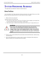
Отзывы: