ProMinent 040830 SST Скачать руководство пользователя страница 47

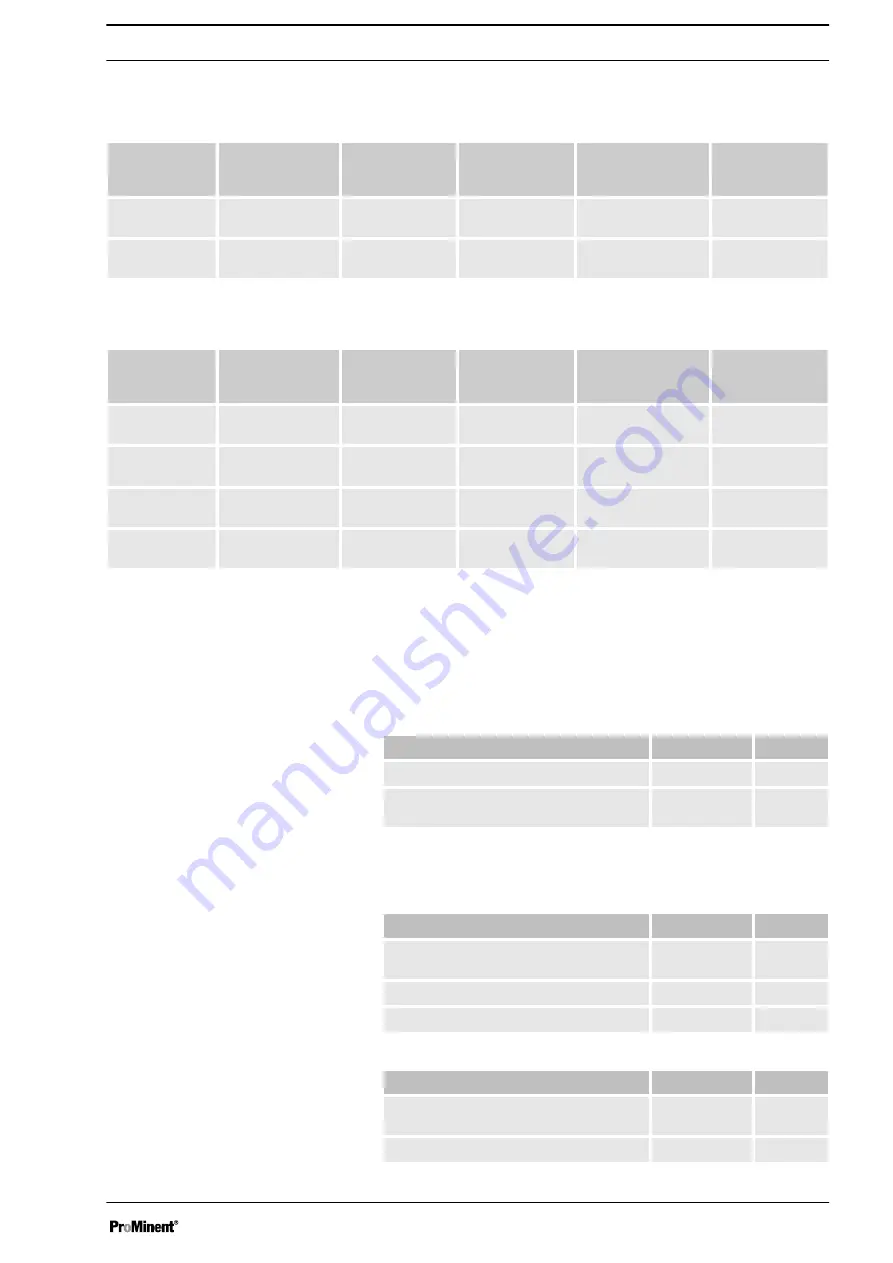
14.3  Wetted materials

DN 25 ball valve

Material version Liquid end, suc‐

tion/pressure con‐

nector

Seals*

Valve balls

Valve seats

Integral relief

valve

PVT

PVDF

PTFE

Glass

PTFE

PVDF / FPM or

EPDM

SST

Stainless steel

1.4581

PTFE

Stainless steel

1.4401

PTFE

Stainless steel /

FPM or EPDM

DN 32 plate valves

Material version Liquid end, suc‐

tion/pressure con‐

nector

Seals*

Valve plates /

valve springs

Valve seats

Integral relief

valve

PPT

PP

PTFE

Ceramic / hast. C

+ CTFE**

PTFE

PVDF / FPM or

EPDM

PCT

PVC

PTFE

Ceramic / hast. C

+ CTFE**

PTFE

PVDF / FPM or

EPDM

PVT

PVDF

PTFE

Ceramic / hast. C

+ CTFE**

PTFE

PVDF / FPM or

EPDM

SST

Stainless steel

1.4581

PTFE

Stainless steel

1.4404 / Hast. C

PTFE

Stainless steel /

FPM or EPDM

* Metering diaphragm is PTFE coated
** The valve spring is coated with CTFE (resistance similar to PTFE)

14.4  Ambient conditions

14.4.1  Ambient temperatures

Data

Value Unit

Storage and transport temperature

-10 ... +50 °C

Ambient temperature in operation (drive +

motor):

-10 ... +45 °C

14.4.2  Media temperatures

Data

Value Unit

Max. temperature long-term at max. oper‐

ating pressure

60 °C

Max. temperature for 15 min at max. 2 bar

100 °C

Minimum temperature

-10 °C

Data

Value Unit

Max. temperature long-term at max. oper‐

ating pressure

45 °C

Max. temperature for 15 min at max. 2 bar

60 °C

Pump, compl.

PP liquid end

PC liquid end

Technical data


47

Содержание 040830 SST

Страница 1: ...s P_SI_0075_SW Original operating instructions 2006 42 EC Part no 985905 BA SI 064 01 14 EN Please carefully read these operating instructions before use Do not discard The operator shall be liable fo...

Страница 2: ...to the correct operation of the unit or is intended to make your work easier Safety notes Safety notes are identified by pictograms see Safety Chapter These operating instructions conform to current E...

Страница 3: ...a 45 14 2 Shipping weight 46 14 3 Wetted materials 47 14 4 Ambient conditions 47 14 4 1 Ambient temperatures 47 14 4 2 Media temperatures 47 14 4 3 Air humidity 48 14 5 Motor data 48 14 6 Stroke actua...

Страница 4: ...DN 32 4 with relief valve FPM seal no valve spring 5 with relief valve FPM seal with valve spring standard for DN 32 6 with relief valve EPDM seal no valve spring 7 with relief valve EPM seal with va...

Страница 5: ...ge NEMA 3 No motor with B 5 size 71 DIN Degree of protection 0 IP 55 standard 1 Exe design ATEX T3 2 Exd version ATEX T4 Stroke sensor 0 No stroke sensor standard 2 Pacing relay reed relay 3 Stroke se...

Страница 6: ...se the pump to meter liquid metering chemicals n In potentially explosive atmospheres in zone 1 device category II 2G explosion group II C only operate the pump with the appropriate nameplate and the...

Страница 7: ...n Technical personnel service Installation electrical Electrical technician Operation Instructed person Maintenance repair Technical personnel service Decommissioning disposal Technical personnel serv...

Страница 8: ...fe elec trical circuits The following information relates essentially to the unique characteristics in areas at risk from explosion but does not replace the standard operating instructions Only clean...

Страница 9: ...down loads CAUTION Danger of personnel injury and material damage The use of untested third party parts can result in personnel injuries and material damage Only fit parts to metering pumps which have...

Страница 10: ...e latest safety data sheet from the supplier for the chemicals resources to be used with the system The operator should create the legal framework for safe operation of the system or system component...

Страница 11: ...storage or transportation The unit should only be stored or transported in a well packaged state preferably in its original packaging Only transport the unit when the red gear bleeding plug is pushed...

Страница 12: ...pment and control elements S3Ba 1 Drive motor 2 Drive unit 3 Stroke length adjustment knob 4 Liquid end with relief valve 5 Diaphragm rupture sensor 1 2 P_SI_0088_SW Fig 4 Sigma control elements 1 Rel...

Страница 13: ...length n 100 4 rotations n 25 1 rotation n 0 5 1 scale mark on stroke adjustment dial PG11 PG9 1 2 3 A B P_SI_0036 Fig 6 Front cover for version with pacing relay A Pacing relay cable B Supply voltag...

Страница 14: ...One cycle is thus completed 4 2 1 5 3 13 Fig 7 Cross section through the liquid end 1 Suction valve 2 Diaphragm 3 Discharge valve 4 Dosing head 5 Backplate 13 Safety diaphragm 5 3 Integral relief valv...

Страница 15: ...in the event of a diaphragm rup ture the lowered red cylinder 6 springs forward beneath the transparent cover 7 so that it then becomes clearly visible see Fig 9 With the electrical diaphragm rupture...

Страница 16: ...te CAUTION Danger from incorrectly operated or inadequately maintained pumps Danger can arise from a poorly accessible pump due to incorrect operation and poor maintenance Ensure that the pump is acce...

Страница 17: ...y too low Vibrations can disrupt the liquid end valves Secure the metering pump so that no vibrations can occur Take the dimensions m for the fastening holes from the appropriate dimensional drawings...

Страница 18: ...y only be transported using stain less steel dosing heads In exceptional cases where this is not possible PTFE with carbon can be used whereby our TT_ versions are manufactured from this conducting pl...

Страница 19: ...ssible operating pressure of the system CAUTION Uncontrolled flow of feed chemical Feed chemicals can leak through a stopped metering pump if there is back pressure Use an injection valve or a vacuum...

Страница 20: ...and then only against impermissible positive pressure that is caused by the metering pump itself It cannot protect the system against positive pressure Protect the motor and gear of the system against...

Страница 21: ...leed func tion is blocked Therefore lead the overflow line back into the storage tank When operating the integral relief valve close to the opening pressure a minimal overflow into the overflow line c...

Страница 22: ...hazardous feed chemicals Hazardous feed chemical can leak out when using conventional bleeding procedures with metering pumps Install a bleed line with a return into the storage tank Shorten the retur...

Страница 23: ...omponents in areas at risk from explosion Note the enclosed documentation for the individual elec trical components WARNING Danger of electric shock Unprofessional installation may lead to electric sh...

Страница 24: ...ion against heating from overloading Ensure that motors are only installed and inspected by a recognisably trained skilled operative in areas at risk from explosion Observe the enclosed operating inst...

Страница 25: ...tors or special motor flanges are possible on request CAUTION Provide a separate power supply for the external fan with motors with external fans identity code specification R or Z Connect up the moto...

Страница 26: ...ng device and that of the stroke sensor see chapter Technical data 1 Install the cable which originates from the pacing relay see the figure in the chapter entitled Overview of equipment and control e...

Страница 27: ...er consumption 230 V AC 180 254 V 50 60 Hz 10 mA at 230 V 50 Hz 115 V AC 90 134 V 50 60 Hz 15 mA at 115 V 60 Hz 24 V DC 20 28 V 10 mA at 24 V DC Install the heating cartridge according to its document...

Страница 28: ...cessary flushing pipes or bleed lines have been connected CAUTION Prior to commissioning check that the power end motor and corresponding ancillary equipment is connected in compli ance with the regul...

Страница 29: ...essure that is caused by the metering pump itself It cannot protect the system against positive pressure Protect the motor and gear of the system against posi tive pressure using other mechanisms Prot...

Страница 30: ...can occur Only adjust the stroke length when the pump is running This is easier and also better for the pump 20 0 0 50 25 75 5 75 0 5 0 25 10 30 P_SI_0095_SW Fig 19 Adjusting the stroke length n 100...

Страница 31: ...ement Only perform tests and repairs in compliance with DIN EN IEC 60079 17 and only permit experienced per sonnel who have the requisite knowledge to perform the work These measures constitute the mi...

Страница 32: ...kits In case of doubt refer to the exploded views and ordering information in the appendix Interval Maintenance work Personnel After approx 5 000 oper ating hours Change gear oil refer to Changing ge...

Страница 33: ...an oil trough under the oil drain plug 2 3 Unscrew the oil drain plug 2 from the power end housing 4 Allow the gear oil to run out of the power end 5 Screw in the oil drain plug 2 with a new seal Fil...

Страница 34: ...pump CAUTION Warning of feed chemical spraying around Feed chemical can spray out of the hydraulic components if they are manipulated or opened due to pressure in the liquid end and adjacent parts of...

Страница 35: ...chnical personnel CAUTION Warning of personal injury and material damage Feed chemical may escape from the liquid end for example if ball valves not repaired correctly Only use new components which fi...

Страница 36: ...With the pump running move the stroke adjustment dial to the stop at 0 stroke length The drive axle is now difficult to turn 3 Switch off the pump 4 Unscrew the hydraulic connectors on the discharge a...

Страница 37: ...ump s fitting position 14 Tighten the screws gently to start with 15 Screw the diaphragm rupture sensor into the dosing head 16 Start up the pump and adjust the stroke length to 100 17 Stop the pump a...

Страница 38: ...nsor Optical diaphragm rupture sensor 1 Unscrew the transparent cover from the diaphragm rupture sensor 2 Press the red cylinder into the diaphragm rupture sensor until it engages 3 Press the piston o...

Страница 39: ...the diaphragm is damaged then feed chemical can escape when there is a dia phragm rupture The piston must not be scratched it must remain com pletely smooth so that during operation it does not damag...

Страница 40: ...ith combustible media These may start to burn when combined with oxygen During filling and draining of the liquid end an expert must ensure that feed chemical does not come into con tact with oxygen W...

Страница 41: ...ncy 2 Wire the motor correctly Electrician The mains voltage has failed Eliminate the cause Electrician Fluid is escaping from the back plate The dosing head screws are no longer tight enough Tighten...

Страница 42: ...e dosing Once the operating membrane has ruptured precise dosing of the pump can no longer be guaranteed Do not continue to use the pump for critical process dosing For uncritical processes the pump c...

Страница 43: ...y notes relating to the Storage Transport and Unpacking chapter are read before shipping or transporting the unit Thoroughly clean the liquid end and the housing of chemicals and dirt Adhere to the sa...

Страница 44: ...g the feed chemical to run out 4 Flush the liquid end with a suitable medium Observe the safety data sheet Flush the dosing head thoroughly when using haz ardous feed chemicals 5 Possible additional w...

Страница 45: ...08 33 7 103 5 2 1 1 2 DN25 120270 PVT 10 292 33 8 144 5 2 1 1 2 DN25 120270 SST 12 292 33 8 144 5 2 1 1 2 DN25 120330 PVT 10 365 33 8 180 5 2 1 1 2 DN25 120330 SST 12 365 33 8 180 5 2 1 1 2 DN25 07041...

Страница 46: ...492 130 86 4 1 2 DN32 070410 SST 7 102 492 130 86 4 1 2 DN32 070580 PVT PPT PCT 7 102 696 183 124 4 1 2 DN32 070580 SST 7 102 696 183 124 4 1 2 DN32 040830 PVT PPT PCT 4 58 1000 264 173 3 1 2 DN32 04...

Страница 47: ...Ceramic hast C CTFE PTFE PVDF FPM or EPDM SST Stainless steel 1 4581 PTFE Stainless steel 1 4404 Hast C PTFE Stainless steel FPM or EPDM Metering diaphragm is PTFE coated The valve spring is coated wi...

Страница 48: ...ameplate Motor data sheets special motors special motor flanges external fan temperature monitoring For further information for the motor with identity code specification S refer to the motor data she...

Страница 49: ...ing to a pro tective low voltage e g in accordance with EN 60335 1 SELV The cable can be connected as required 5 25 V DC in accordance with Namur or DIN 60947 5 6 potential free design Data Value Unit...

Страница 50: ...ctive surface cov ered 1 mA Rated switching distance 1 5 mm Ri 1 k Cable colour Polarity blue brown 14 10 Relay The electrical data for the relay are contained in the chapter Installation electrical 1...

Страница 51: ...umber During operation with an automatic stroke length adjustment control together with a variable speed motor the stroke rate must not fall below 30 strokes min Otherwise technical problems occur bec...

Страница 52: ...4 2 500 0 1100 1000 900 800 700 600 300 400 100 200 041030 040830 070580 070410 0 20 40 60 10 30 50 80 70 90 100 300 0 500 400 100 200 120270 120190 120145 0 1 6 10 12 9 7 5 0 300 500 400 100 11 8 4 3...

Страница 53: ...16 Dimensional drawings Compare the dimensions on the dimension sheet and pump All dimensions are in mm Dimensional drawings 53...

Страница 54: ...Dimensional drawings 54...

Страница 55: ...Dimensional drawings 55...

Страница 56: ...Dimensional drawings 56...

Страница 57: ...Dimensional drawings 57...

Страница 58: ...145 120190 120270 120330 1 Spring 2 Ball 3 Ball seat 4 Diaphragm rupture sensor visual 1033323 5 Valve 740615 6 Multi layer diaphragm 1029604 The items listed are included in the spare parts kit Speci...

Страница 59: ...Type 070410 070580 040830 041030 1 Spring 2 Ball 3 Ball seat 4 Diaphragm rupture sensor visual 1033323 5 Valve 1002806 6 Multi layer diaphragm 1029603 The items listed are included in the spare parts...

Страница 60: ...0830 041030 10 Relief valve compl 10 bar PVA 1005626 10 Relief valve compl 7 bar PVA 1004801 10 Relief valve compl 4 bar PVA 1004778 The items listed are included in the spare parts kit Springs made f...

Страница 61: ...70 120330 1 Spring 2 Ball 3 Ball seat 4 Diaphragm rupture sensor visual 1033323 5 Valve 803708 6 Multi layer diaphragm 1029604 The items listed are included in the spare parts kit Special accessories...

Страница 62: ...tion Type 070410 070580 040830 041030 1 Spring 2 Ball 3 Ball seat 4 Diaphragm rupture sensor visual 1033323 5 Valve 1002811 6 Multi layer diaphragm 1029603 The items listed are included in the spare p...

Страница 63: ...830 041030 10 Relief valve compl 12 bar SSA 1005625 10 Relief valve compl 7 bar SSA 1005042 10 Relief valve compl 4 bar SSA 1005038 The items listed are included in the spare parts kit Springs made fr...

Страница 64: ...gs Spare parts kit for material ver sion Seals Part no SPK PRV 4 bar PVT SST PTFE 1031204 SPK PRV 7 bar PVT SST PTFE 1031205 SPK PRV 10 bar PVT PTFE 1031201 Scope of supply see exploded view drawings...

Страница 65: ...ith 2 complete valves 1046480 Material version Liquid end Suction pressure connector Seals ball seat Balls Integral bleed valve or relief valve PVT PVDF PVDF PTFE PVDF Glass PVDF EPDM SST Stainless st...

Страница 66: ...the version distributed by us This declaration loses its validity in the event of a modification to the product not agreed with us Designation of the product Metering pump Sigma product range Product...

Страница 67: ...Y 1 or 2 or X 1 2 or 3 and Y A or X V and Y 2 Serial number refer to nameplate on the device Relevant EC directives EC Machinery Directive 2006 42 EC EC EMC Directive 2004 108 EC EC Explosion Preventi...

Страница 68: ...986270 1 en_GB 2011 ProMinent Dosiertechnik GmbH Im Schuhmachergewann 5 11 69123 Heidelberg Germany Telephone 49 6221 842 0 Fax 49 6221 842 612 email info prominent com Internet www prominent com...

Отзывы: