background image

7

HERO H100F

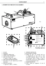
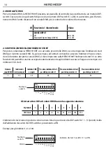
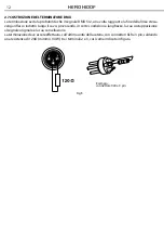
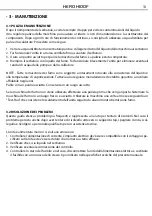
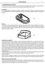
Receiver

The receiver is tested and pre-attached to the rear panel of each HERO-series model. Please do not try to 

remove it. The receiver responds to up to 5 different transmitters that are registered with the machine. The 

included transmitter has been registered with the machine before shipment. It can be directly operated 

without any start-up setting.

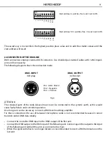
A

B

Registering transmitters

To operate the machine with a different transmitter than the included one, or to operate it with up to 5 

different transmitters, each transmitter must be registered first. There is an LED light on the rear control 

panel of the machine. When the machine is turned on, the green LED will be flashing for 15 seconds. Dur-

ing the 15-second interval, users can register signals for one or more transmitters. For this purpose, press 

the button “A” on each transmitter. If the registering signals of the transmitters are well received by the re-

ceiver, the green LED will stop flashing and light permanently. The previous transmitters are cleared from 

the memory of the receiver. If no transmitter is registered while the machine is switched on, the memory 

of the receiver will keep the record of the previous operation.

Setting Example 1:

In order to register several transmitters with a machine, turn on the machine. While the green LED is flash-

ing, press the button “A” on each transmitter to establish the signal transmission.

Setting Example 2:

In order to use 1 transmitter to control 2 or more machines, turn on the machines at the same time. While 

the green LEDs are flashing, press the button “A” on the transmitter to establish the signal transmission.

Battery change on the transmitter

If the range of the transmitter decreases, the battery is probably exhausted and must be replaced. For this 

purpose, take off the housing cover and remove the used battery. Insert a fresh 12 V battery, type 23A as 

indicated in the battery compartment and refit the housing cover.

Fig.2

Fig.3

2.3 WIRELESS REMOTE CONTROL

The wireless remote control system consists of a transmitter equipped with two buttons for fog output on 

and off, and a receiver pre-attached to the rear panel of each HERO-series model.

Transmitter

With the transmitter it is possible to emit fog via radio over a distance of up to 50 meters. The transmit-

ter is compatible to any receiver of the HERO-series and can control an unlimited number of machines in 

parallel.

Содержание HERO H100F

Страница 1: ...EN IT Manuale Utente User Manual HERO H100F FOG MACHINE ...

Страница 2: ...ate nel presente manuale di istruzioni Tutte le revisioni e gli aggiornamenti sono disponibili nella sezione Manuali sul sito www musiclights it All rights reserved by Music Lights S r l No part of this instruction manual may be Reproduced in any form or by any means for any commercial use In order to improve the quality of products Music Lights S r l reserves the right to modify the characteristi...

Страница 3: ...rizione 1 2 Specifiche tecniche 1 3 Elementi di comando e di collegamento 2 Funzioni e impostazioni 2 1 Impostazione base 2 2 Funzionamento 2 3 Sistema di controllo wireless 2 4 Modailtà DMX 2 5 Impostazione dell indirizzo di start 2 6 Collegamenti della linea DMX 2 7 Costruzione del terminatore DMX 3 Manutenzione 3 1 Pulizia e manutenzione 3 2 Risoluzione dei problemi Certificato di garanzia 4 4 ...

Страница 4: ...llici Non smontare e non apportare modifiche all unità Tutti gli interventi devono essere sempre e solo effettuati da personale tecnico qualificato Rivolgersi al più vicino centro di assistenza tecnica autorizzato Se si desidera eliminare il dispositivo definitivamente consegnarlo per lo smaltimento ad un istituzione locale per il riciclaggio Attenzioni e precauzioni per l installazione Questo pro...

Страница 5: ...a rischio e pericolo del distributore clien te Eventuali avarie e danni dovranno essere contestati al vettore Ogni reclamo per imballi manomessi dovrà essere inoltrato entro 8 giorni dal ricevimento della merce Garanzie e resi Il prodotto è coperto da garanzia in base alle vigenti normative Sul sito www musiclights it è possibile consultare il testo integrale delle Condizioni Generali di Garanzia ...

Страница 6: ...etica Nonostante le dimensioni contenute H100F si dimostra essere una macchina fumo professionale e dal funzionamento accessibile a chiunque 1 2 SPECIFICHE TECNICHE Alimentazione AC 220 240V 50 60 Hz Caldaia 1000W Emissione 10 000 cu ft min Preriscaldamento prima accensione 11 min Capacità tanica liquido 2 8L Consumo di liquido 11min 1L 100 Output Wireless remote controller incluso DMX on board Pe...

Страница 7: ... BETREIBEN N UR I N I NNENRÄUMEN V ERWENDEN V O R N ÄSSE SC HÜTZEN K EINE ZU WARTENDEN TEILE I M G ERÄTEINNEREN DMX 5 1 2 DIP S WITC H DMX D IP SW C H SW 1 2 3 4 5 6 7 8 9 1 2 4 8 16 32 64 128 256 WIRELESS REC EIVER PO WER I NPUT FUSE DMX I N DMX O UT PO WER S WITC H O N O FF WIRELESS D M X SIG NAL LIG HT ON 1 2 3 4 5 6 7 8 9 2 3 4 1 Fig 1 Pannello posteriore A B 1 UGELLO 2 MANIGLIA 3 SERBATOIO PO...

Страница 8: ...ell unità su ON La macchina entrerà in funzione Durante il tempo di riscaldamento non può essere effettuata nessuna erogazione di fumo Quando la luce verde lampeggerà il processo di riscaldamento è completato L unità è pronta per l uso 3 Per il funzionamento mediante controller wireless far riferimento alle impostazioni indicate nel relativo paragrafo Importante Durante il funzionamento monitorare...

Страница 9: ...catore LED verde lampeggia per 15 secondi Durante il secondo intervallo di 15 secondi è possibile associare il segnale di uno o più trasmettitori A questo scopo premere il tasto A su ogni trasmettitore Se i segnali dei trasmettitori vengono associati al ricevitore l indicatore LED verde smetterà di lampeggiare e si illumi nerà in modo permanente In questo modo i trasmettitori precedentemente assoc...

Страница 10: ...uno dei singoli switch dispone di un numero DIP switch 1 a 9 In particolare per il funzio namento DMX l unità dispone di un canale DMX per il controllo del volume di emissione 2 5 IMPOSTAZIONE DELL INDIRIZZO DI START Per poter comandare la HERO H100F con un unità di controllo DMX occorre impostare l indirizzo di start DMX per il primo canale DMX Se per esempio sull unità di comando è previsto l in...

Страница 11: ...rtato di seguito ATTENZIONE La parte schermata del cavo calza non deve mai essere collegata alla terra dell impianto ciò comporte rebbe malfunzionamenti delle unità e dei controller Per passaggi lunghi può essere necessario l inserimento di un amplificatore DMX In tal caso è sconsigliato utilizzare nei collegamenti cavo bilanciato microfonico poiché non è in grado di trasmettere in modo affidabile...

Страница 12: ...lesso indietro lungo il cavo provocando in certe condizioni e lunghezze la sua sovrapposizione al segnale originale e la sua cancellazione La terminazione deve essere effettuata sull ultima unità della catena con connettori XLR a 3 pin saldando una resistenza di 120Ω minimo 1 4W tra i terminali 2 e 3 così come indicato in figura Esempio connettore XLR a 3 pin Fig 5 ...

Страница 13: ... affidabile negli anni Pulire con un panno asciutto Conservare in un luogo asciutto Se la macchina del fumo non viene utilizzata effettuare una pulizia prima che venga riposta Sistemare la macchina del fumo in un luogo fresco e asciutto Utilizzare la macchina una volta al mese eseguendo un Test Run che consiste nel riscaldamento dell unità seguito da alcuni minuti di emissione fumo 3 2 RISOLUZIONE...

Страница 14: ......

Страница 15: ...1 Introduction 1 1 Description 1 2 Technical specifications 1 3 Operating elements and connections 2 Functions and settings 2 1 Basic 2 2 Operation 2 3 Wireless remote control 2 4 DMX mode 2 5 Adjusting the start address 2 6 Connection of the dmx line 2 7 Construction of the DMX termination 3 Maintenance 3 1 Cleaning and storage 3 2 Trouble shooting Warranty 2 2 3 4 4 5 6 6 7 8 8 9 10 11 11 ...

Страница 16: ...work must always be carried out by qualified technical personnel Contact the nearest sales point for an inspection or contact the manufacturer directly If the unit is to be put out of operation definitively take it to a local recycling plant for a disposal which is not harmful to the environment Warnings and installation precautions For inside use only Not designed for outside use Always unplug yo...

Страница 17: ...roken packs will have to be forwarded within 8 days from the reception of the goods Warranty and returns The guarantee covers the fixture in compliance with existing regulations You can find the full version of the General Guarantee Conditions on our web site www musiclights it Please remember to register the piece of equipment soon after you purchase it logging on www musiclights it The product c...

Страница 18: ...el in terms of good quality fog and energy efficiency In conclusion H100D bring users to a professional scene in an easier method 1 2 TECHNICAL SPECIFICATIONS Power AC 220 240V 50 60 Hz Heater 1000W Output 10 000 cu ft min First Heat up Time 11 min Tank Capacity 2 8 liter Fluid Consumption Rate 11 min 1L 100 Output Remote Included Wireless Remote DMX on board Weight 11 4 kg Dimensions mm L468 W250...

Страница 19: ...WAC HSENEN G ESTATTET N IEMALS O HNE FLUID BETREIBEN N UR I N I NNENRÄUMEN V ERWENDEN V O R N ÄSSE SC HÜTZEN K EINE ZU WARTENDEN TEILE I M G ERÄTEINNEREN DMX 5 1 2 DIP S WITC H DMX D IP SW C H SW 1 2 3 4 5 6 7 8 9 1 2 4 8 16 32 64 128 256 WIRELESS REC EIVER PO WER I NPUT FUSE DMX I N DMX O UT PO WER S WITC H O N O FF WIRELESS D M X SIG NAL LIG HT ON 1 2 3 4 5 6 7 8 9 2 3 4 1 Fig 1 Rear panel A B 1...

Страница 20: ...er switch to ON on the back of the machine The unit will start to warm up the machine During this time the machine cannot generate any fog The green light will flash and stay ON when the warm up process is complete 3 Please now refer below of instructions of Wireless Remote for setting for the remote controller com mand Important Always monitor tank fluid level as you are fogging Never drink Fog l...

Страница 21: ...he machine is switched on the memory of the receiver will keep the record of the previous operation Setting Example 1 In order to register several transmitters with a machine turn on the machine While the green LED is flash ing press the button A on each transmitter to establish the signal transmission Setting Example 2 In order to use 1 transmitter to control 2 or more machines turn on the machin...

Страница 22: ...st DMX channel adjust the start address 33 on the HERO H100F The other functions of the light effect panel are then automati cally assigned to the following addresses An example with the start address 33 is shown below Number of DMX channels Start address example DMX Address occupied Next possible start address for unit No 1 Next possible start address for unit No 2 Next possible start address for...

Страница 23: ...st never be connected to the system s earth as this would cause faulty fixture and controller operation Over long runs can be necessary to insert a DMX level matching amplifier For those connections the use of balanced microphone cable is not recommended because it cannot transmit control DMX data reliably Connect the controller DMX input to the DMX output of the first unit Connect the DMX output ...

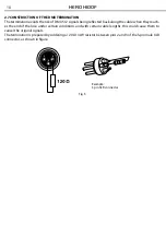
Страница 24: ...ong the cable when they reach es the end of the line under certain conditions and with certain cable lengths this could cause them to cancel the original signals The termination is prepared by soldering a 120Ω 1 4W resistor between pins 2 and 3 of the 5 pin male XLR connector as shown in figure Example 3 pin XLR connector Fig 5 ...

Страница 25: ...es are prone to clogging due to the thick consistency of fog liquid and the high temperature at which it vaporizes However a properly maintained fog machine should provide years of reliable use Clean with a dry cloth only Store dry If the fog machine is not in use please clean it before storage Store the fog machine in a dry and cool place At least operate the fog machine once a month A test run c...

Страница 26: ......

Страница 27: ...chi conseguenti sono a carico del possessore dell apparecchio A tutti gli effetti la validità della garanzia è avallata unicamente dalla presentazione del certificato di garanzia The guarantee covers the unit in compliance with existing regulations You can find the full version of the General Guarantee Conditions on our web site www musiclights it Abstract General Guarantee Conditions Please remem...

Страница 28: ...date Data acquisto FORM TO BE FILLED IN AND MAILED CEDOLA DA COMPILARE E SPEDIRE FORM TO BE FILLED IN AND KEPT CEDOLA DA COMPILARE E CONSERVARE PROV ZIP CODE C A P MODEL MODELLO SERIAL N SERIE N Purchased by Acquistato da SURNAME COGNOME Dealer s stamp and signature Timbro e firma del Rivenditore NAME NOME ADDRESS VIA N CITY CITTà Purchasing date Data acquisto PROV ZIP CODE C A P ...

Страница 29: ......

Страница 30: ......

Страница 31: ......

Страница 32: ...39 0771 721955 www musiclights it info musiclights it Music Lights S r l entertainment technologies ISO 9001 2008 Certified Company 2012 Music Lights S r l PROLIGHTS è un brand di proprietà della Music Lights S r l PROLIGHTS is a brand of Music Lights S r l company ...

Отзывы: