

1.5.2
M o u n t i n g i n s t r u c t i o n
Specifications are subject to change without prior notice. Version 11/2002
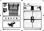
M o u n t i n g
E q u i p m e n t
M o u n t i n g
B
D
A
E
C
D
C
B
(4x)
B
A
(8x)
E
(4x)
D
(4x)
(4x)
C
1.5.2
M o u n t i n g i n s t r u c t i o n
30
50
180
187
L1
L2
L3
4
L4
180
130
Ø 9
W i r i n g
Projectieschermen mogen nooit parallel geschakeld worden. Centrale bediening is alleen mogelijk door speciaal hiervoor ontwikkelde relaiskastjes.
Do not wire two or more screens to one switch. Group control is only possible with specific relais or remote controls.
Projektionswände sollen niemals parallel geschaltet werden. Zentralbedienung ist nur möglich mit speziell dafür entwickelte Relais oder Fernbedienungen.
Der Anschluss dieser Leinwand darf nur von einer autorisierten Fachkraft ausgeübt werden.
Ne pas brancher deux ou plusieurs écrans sur le même inverseur. Il faut pour cela utiliser une commande groupée spécialle.
F
D
E
NL
Main
230V
(Blauw / Blue / Blau / Blue)
(Bruin / Brown / Braun / Brun)
(Geel + Groen / Green /
Gelb + Grün / Jaune + Vert)
2
3
1
4
4
3
2
1
(Blauw / Blue /
Blau / Blue)
(Bruin / Brown /
Braun / Brun)
(Zwart / Black /
Schwarz / Noir)
(Geel + Groen / Green /
Gelb + Grün / Jaune + Vert)
220 V
Switch
A d j u s t i n g
Screen size
Dimensions
(in mm)
L1
L4
350x350cm
3674
3644
3604
3580
300x400cm
4174
4144
4104
4080
350x400cm
4174
4144
4104
4080
400x400cm
4174
4144
4104
4080
350x450cm
4674
4644
4604
4580
365x500cm
5174
5144
5104
5080
L2
L3
Afstellen in- en uitloop doek:
Bij ieder door ons geleverd projectiescherm zijn de instellingen voor
in- en uitloop van het doek afgesteld. Indien noodzakelijk zijn deze te
corrigeren. Hiertoe dient de voorkap gedemonteerd te worden.
Pijl nr. 1:
Bepaalt de eindpositie van het doek bij INROLLEN.
Draaien in de + richting resulteert in het verder inlopen van het
doek.
Pijl nr. 2:
Bepaalt de eindpositie van het doek bij UITROLLEN.
Draaien in de + richting resulteert in het verder uitlopen van het
doek.
Indien de motor in de verkeerde richting loopt, verwissel dan de zwarte
en bruine draad in de schakelaar (2 en 3).
LET OP:
• Één omwenteling met stelknop 1 of 2 betekent ca. 3 cm
doek in- of uitloop. Pas op bij afstelling van de eindpositie
bij inrollen ter voorkoming van schade.
• Ter eindcontrole is het nodig het doek eenmaal helemaal
in en uit te laten lopen.
Adjusting screen height settings:
Every electric projection screen is supplied with pre-set
up- and down end positions.
If necessary these are adjustable. Remove the front cover
for this purpose.
Arrow n
o
1: Sets the UP limit position of the screen. Turn to
the positive (+) direction to further retract
screen surface.
Arrow n
o
2: Sets the DOWN limit position of the screen.
Turn to the positive (+) direction to further lower the screen
surface.
If the screen is not operating in accordance with the direction of the
arrows, reverse the black and brown motor leads (2 and 3) connected to
the switch.
WARNING:
• One turn of the adjusting screws equals appr. 3 centimeters/1 inch of
screen material rolling up or down. Be carefull adjusting the UP
position to prevent damage to the screen fabric.
• Check the correct settings by fully rolling the screen in- and out once.
E
NL
Einstellung der Endpositionen:
Jede Projektionswand ist fertig zum Einsatz.
Falls erforderlich sind die Positionen zum Auf- und Abrollen des Tuches
zu korrigieren. Hierzu soll das vordere Teil des Kastens abmontiert werden.
Pfeil 1: Bestimmt die Endposition der Leinwand beim einrollen.
Drehung in “+” -Richtung damit das Tuch weiter einrollt.
Pfeil 2: Bestimmt die Endposition der Leinwand beim ausrollen.
Drehung in “+” -Richtung damit das Tuch weiter ausrollt.
Wenn der Motor eine falsche Drehrichtung aufweist, sollen die schwarze
und braune Kabel (2 und 3) verwechselt werden.
VORSICHT:
• Eine Drehung mit Einstellknopf 1 oder 2 ergibt ± 3 cm
Ein- oder Ablauf des Tuches. Vorsicht ist erfordert bei der
Einstellung der Aufwärtsposition um Beschädigung des
Tuches zu vermeiden.
• Zur Endkontrolle der Endpositionen ist es erforderlich, die
Leinwand einmal vollständig ein- und ausrollen zu lassen.
Réglage des fins de courses:
Dans chaque écran électrique les positions haute et
basse de la toile sont déjà mis.
Si nécessaire il est possible de corriger des fins de courses.
Dans ce cas le carter frontal du écran doit être demonté.
Flèche n
o
1: Pour régler la position haute de la toile.
Tourner la molette dans le sens “+” pour
s’enrouler la toile.
Flèche n
o
2: Pour régler la position basse de la toile.
Tourner la molette dans le sens “-“pour se
dérouler la toile.
Si le moteur tourne dans le mauvais sens, inversez les fils noir et marron
(2 et 3) au niveau de l’inverseur mutateur.
ATTENTION:
• Un tour de la molette correspond à ± 3 cm d'enroulement ou de
déroulement de la toile. Régler la position de haute avec prudence!
• Pour une vérification finale, il faut enrouler et dérouler la toile une fois
entièrement.
F
D
1
2
+
+
2
1
4148 1.5.2-ElprolLarge 15-11-2002 12:06 Pagina 3


