background image

Содержание 831.24824.6

Страница 1: ...6 Serial No Write the serial number in the space above for future reference Serial Number Decal Assembly Operation Maintenance Part List and Drawing Sears Roebuck and Co Hoffman Estates IL 60179 TR A ILL User s SE Manual ...

Страница 2: ...e replacement decal Apply the decal in the location shown Note The decals may not be shown at actual size KEEPHANDS ANDFEET AWAY FROMTHISAREA WHILETHE TREADMILL IS INOPERATION Prolect yourself and others from risk of serious injury Read the user s manual and Stand only on the s_de rails when sta fln_ or stopping treadmill Hold ha drails to prevent fall_ng and always wear the safety clip wile ope_a...

Страница 3: ...ch may result in a fall and serious injury Keep the power cord and the surge suppres sor away from heated surfaces Do not operate the treadmill where aerosol products are used or where oxygen is being administered Keep children under age 12 and pets away from the treadmill at all times 14 Never move the walking belt while the power is turned off Do not operate the treadmill if the power cord or pl...

Страница 4: ...tion 22 Never insert any object into any opening on the treadmill 23 Inspect and properly tighten all parts of the treadmill regularly SAVE THESE 24 25 26 DANG ER A ways unplug the power cord immediately after use beforecleaning the treadmill and before performing the mainte nance and adjustment procedures described in this manual Never remove the motor hood un less instructed to do so by an autho...

Страница 5: ...using the treadmill If you have questions after read ing this manual please see the back cover of this manual To help us assist you please note the product model number and serial number before contacting us The model number and the location of the serial num ber decal are shown on the front cover of this manual Before reading further please review the drawing below and familiarize yourself with t...

Страница 6: ...d your own Phillips screwdriver _ adjustable wrench _ and scissors _ Use the drawings below to identify the assembly hardware The number in parentheses below each drawing is the key number of the part from the PART LIST near the end of this manual The number after the parentheses is the quantity needed for assembly Note If a part is not in the hardware kit check to see if it is preattached to one ...

Страница 7: ...he shipping bracket B Cut the shipping tie securing the Wire Harness 92 to the Base 99 Next locate a tie in the in dicated hole in the Base and use the tie to pull the Wire Harness out of the hole See the inset drawing Cut off the end of the tie I1 57 92 B 99 Hole Tie Cut Attach two Base Feet 93 to the Base 99 in the locations shown with two M4 2 x 25mm Tek Screws 2 and two Base Foot Spacers 94 At...

Страница 8: ... 80 near the Base 99 See the inset drawing Tie the wire tie in the Right Upright securely around the end of the Wire Harness 92 Then pull the other end of the wire tie until the Wire Harness is routed completely through the Right Upright 92 o Wire Tie Wire Tie 80 92 Hold a Bolt Spacer 98 inside the lower end of the Right Upright 80 Insert an M10 x 96mm Bolt 7 with an M10 Star Washer 8 into the Rig...

Страница 9: ...more stable do not fully fold the Frame yet Remove and discard the two indicated bolts A and the shipping bracket B Remove the M10 Locknut 36 the M10 x 50mm Bolt 26 and the shipping bracket C from the Base 99 Attach a Wheel 95 with the Bolt and the Locknut that you just removed Do not over tighten the Locknut the Wheel must turn freely Discard the shipping bracket 95 26 36 57 9 ...

Страница 10: ...dmill so that the Base 99 is flat on the floor 91 99 10 Set the console assembly face down on a soft surface to avoid scratching the console assembly Identify the Right Handrail 100 which is marked with a sticker Hold the Right Handrail near the console assembly Attach the console ground wire to the Right Handrail with a 8 x 1 2 Ground Screw 29 Next insert the console wire into the large hole in t...

Страница 11: ...2 to the console wire See the inset drawing The connectors should slide together easily and snap into place if they do not turn one connector and try again IF THE CONNECTORS ARE NOT CON NECTED PROPERLY THE CONSOLE MAY BE DAMAGED WHEN THE POWER IS TURNED ON Remove the wire tie from the Wire Harness Then insert the connectors into the Right Upright 80 Set the console assembly on the Right Upright 80...

Страница 12: ... that the 3 8 x 4 3 4 Bolt 3 stays inside of the resistance mechanism and that the resistance mecha nism does not come apart Note See the lower drawing to reassemble the resistance mechanism if necessary Apply a small amount of the included grease around the Resistance Cone 85 Insert the Resistance Cone into the Upright insert 84 in the Left Upright 79 with the two large holes on top as shown Then...

Страница 13: ...ob 55 are in the posi tions shown Attach the upper end of the Storage Latch 54 to the Frame 57 with a 3 8 x 1 3 4 Bolt 6 and a 3 8 Jam Nut 5 Attach the lower end of the Storage Latch 54 to the Base 99 with a 3 8 x 1 3 4 Bolt 6 Note It may be necessary to move the Frame 57 back and forth to align the Storage Latch with the Base Lower the Frame 57 see HOW TO LOWER THE TREADMILL FOR USE on page 21 16...

Страница 14: ...ressor to indicate whether it is functioning properly Failure to use a properly functioning surge suppressor could result in damage to the control system of the treadmill If the control system is damaged the walking belt may slow accelerate or stop unexpectedly which may result in a fall and serious injury This product must be grounded if it should malfunc tion or break down grounding provides a p...

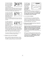
Страница 15: ...x preset iFit crosswalk workouts that automatically control the speed and incline of the treadmill and prompt you to use the crosswalk arms for a total body workout To turn on the power see page 16 To use the man ual mode see page 16 To use a preset workout see page 18 To use the information mode see page 19 iMPORTANT If there is a sheet of clear plastic on the face of the console remove the plast...

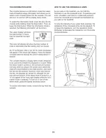
Страница 16: ...rted the manual mode will be selected If you have selected a workout press either of the Workout buttons re peatedly until only zeros appear in the displays t t l 1 1 U UU t 3 t I t 3 t 3 t 3 t 3 LJ U U U OST LJ LJ SPEEO To start the walking belt press the Start button the Speed increase button or one of the ten numbered speed buttons If you press the Start button or the Speed increase button the ...

Страница 17: ...g the handgrip pulse sensor remove the sheets of clear plastic from the metal contacts In addition make sure that your hands are clean To measure your heart rate stand on the foot rails and place your hands on the metal contacts avoid moving your hands When your pulse is detected the heart symbol in the display will begin to flash one or two dashes will appear and then your heart rate will be show...

Страница 18: ...s of tones will sound and the next segment of the profile will begin to flash If a different speed or incline setting is pro grammed for the next segment the speed or in cline setting will flash in the display to alert you If you have selected a crosswalk workout you will be prompted to use the crosswalk arms When the crosswalk indicator on the console lights up move the crosswalk arms forward and...

Страница 19: ...emo mode designed to be used if the treadmill is displayed in a store While the demo mode is turned on the console will function normally when you plug in the power cord switch the reset off circuit breaker to the reset position and insert the key into the console However when you remove the key the displays will remain lit although the but tons will not function If the demo mode is turned on a d ...

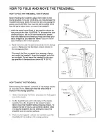
Страница 20: ... the latch knob is locked in the storage position To protect the floor or carpet from damage place a mat under the treadmill Keep the treadmill out of di rect sunlight Do not leave the treadmill in the stor age position in temperatures above 85 F 30 C Frame t Latch Knob HOW TO MOVE THE TREADMILL Before moving the treadmill convert it to the storage position as described above Make sure that the la...

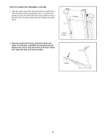
Страница 21: ...ay be nec essary to push the frame forward as you pull the knob to the left Pivot the frame downward and release the latch knob Latch Knob 2 Hold the metal frame firmly with both hands and lower it to the floor CAUTION Do not grip only the plastic foot rails or drop the frame to the floor Bend your legs and keep your back straight Frame 21 ...

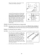
Страница 22: ...it breaker has tripped wait for five minutes and then press the switch back in b Make sure that the power cord is plugged in If the power cord is plugged in unplug it wait for five minutes and then plug it back in c Remove the key from the console Reinsert the key into the console d If the treadmill still will not run please see the back cover of this manual PROBLEM The console displays remain lit...

Страница 23: ...y After a few seconds re insert the key The treadmill will automatically rise to the maximum incline level and then return to the minimum level This will recalibrate the incline system PROBLEM The walking belt slows when walked on SOLUTION a Use only a single outlet surge suppressor that meets all of the specifications described on page 14 b If the walking belt is overtightened treadmill perfor ma...

Страница 24: ...idler roller bolts clock wise 1 4 of a turn When the walking belt is cor rectly tightened you should be able to lift each side of the walking belt 2 to 3 in 5 to 7 cm off the walking platform Be careful to keep the walking belt centered Then plug in the power cord insert the key and carefully walk on the treadmill for a few minutes Repeat until the walking belt is prop erly tightened PROBLEM The c...

Страница 25: ...During the first few minutes of exercise your body uses carbohydrate calories for energy Only after the first few minutes of exercise does your body begin to use stored fat calories for energy if your goal is to burn fat adjust the intensity of your exercise until your heart rate is near the lowest number in your training zone For maximum fat burning exercise with your heart rate near the middle n...

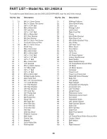
Страница 26: ...3 8 Flange Nut 85 36 4 M10 Locknut 86 37 2 M8 Flange Nut 87 38 3 Hood Clip 88 39 4 M8 Cage Nut 89 40 1 6mm Hex Key 90 41 1 4mm Hex Key 91 42 1 5mm Hex Key 92 43 1 Hex Key 93 44 1 Warning Decal 94 45 2 Platform Cushion 95 46 2 Belt Guide 96 47 2 Frame Cap 97 48 1 Magnet 98 49 1 Drive Roller Belt 99 50 1 Walking Belt 100 1 1 1 1 1 1 1 2 1 2 1 1 1 1 3 1 2 1 1 1 1 1 1 1 1 1 1 1 1 1 2 2 1 2 2 2 2 2 1 1...

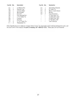
Страница 27: ... Foot Rail Decal 106 1 Fan Housing Fan 12 Blue Wire 2F 107 1 7 1 2 Cable Tie 10 Blue Wire M F 108 1 Console 4 Black Wire M F 109 1 Key Clip 8 Red Wire M F 110 3 15 1 2 Cable Tie User s Manual 111 2 Releasable Tie Note Specifications are subject to change without notice For information about ordering replacement parts see the back cover of this manual If a part is missing call 1 888 533 1333 These ...

Страница 28: ...o0 44 28 83 40 41 42 43 28 16 5O 57 3O 31 55 51 56 54 52 47 16 22 53 6 X 1 0 0 0 0 m Z 63 I 0 m Z 0 O_ a 33 o o0 o CO ...

Страница 29: ...EXPLODED DRAWING B mModel No 831 24824 6 ROSOgA 63 33 36 25 10 73 34 10 10 65 29 ...

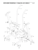
Страница 30: ...EXPLODED DRAWING CmModel No 831 24824 6 ROSOgA 4 7 8 96_ 114 i 95 84 98 1 92 85 86 _ 3 87 89 95 3 19 13 92 99 30 87 85 1 4 91 8 ...

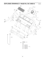
Страница 31: ...EXPLODED DRAWING DmModel No 831 24824 6 Roso9A 105 21 102 108 _109 104 102 110 113 29 100 12 _107 102 31 ...

Страница 32: ...air Center 1 800 488 1222 Call anytime day or night U S A only www sears com To purchase a protection agreement U S A or maintenance agreement Canada on a product serviced by Sears 1 800 827 6655 U S A 1 800 361 6665 Canada iiiiiiiiiiiiiiiii iiiiiiiiiiiiiiiii iiiiiiiiiiiiiiiii iiiiiiiiiiiiiiiii iiiiiiiiiiiiiiiii iiiiiiiiiiiiiiiii iiiiiiiiiiiiiiiii iiiiiiiiiiiiiiiii iiiiiiiiiiiiiiiii iiiiiiiiiiiiii...

Отзывы: