background image

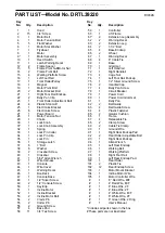
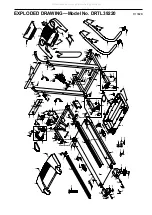
PART LIST—Model No. DRTL39220

R1002B

Key 

No.

Qty.

Description

Key 

No.

Qty.

Description

1

1

Hood

2

153/4” Screw

3

1

Motor Belt

4

1

Motor Tension Bolt

55Flat Washer
6

1

Motor Star Washer

7

1

Flywheel

8

1

Motor

9*

1

Motor Assembly

10

1

Reed Switch

11

1

Latch Warning Decal

12

2

Frame Spacer

13

5Frame Pivot Nut/Motor Nut

14

2

Frame Pivot Bolt

154

Walking Platform Screw

16

1

Left Foot Rail

17

1

Front Roller/Pulley

18

1

Magnet

19

1

Motor Pivot Bolt

20

2

Motor Bracket Bolt

21

1

Right Foot Rail Endcap

22

2

Belly Pan Clip

23

1

Front Roller Adjustment Bolt

24

4

Plastic Stand-off

251

Electronics Bracket

26

6

Electronics Screw

27

1

Power Board

28

1

Motor Tension Nut

29

1

Choke

30

1

Lock Knob

31*

1

Lock Knob Assembly

32

1

Spring

33

1

Lock Pin Collar

34

1

Lock Pin Clip

351

Lock Pin

36

1

Storage Latch

37

6

1” Bolt

38

6

Washer

39

2

Crossbar Screw

40

1

Crossbar

41

1

5/32” Allen Wrench

42

1

Wire Harness

43

1

Console

44

1

Wire Cover

451

Warning Decal

46

1

Bookrack

47

1

Console Base

48

1

1/2” Silver Screw

49

2

1/2” Console Screw

50

1

Key/Clip

51

1

Incline Motor

52

1

Incline Bracket

53

2

Incline Motor Bolt

54

2

Clevis Pin

55

2

Cotter Pin

56

2

Ground Screw

57

4

Base Pad

58

11

3/4” Tek Screw

59

1

Controller

60

1

Lift Frame

61*

2

Extension Leg Assembly

62

2

Warning Decal

63

2

Extension Leg

64

2

3 1/2” Bolt

654

Base Endcap

66

2

Wheel

67

1

Warning Decal

68

4

8” Cable Tie

69

1

Base

70

1

Grommet

71

1

Left Handrail

72

1

Right Handrail

73

4

Cage Nut

74

1

Left Foot Rail Endcap

751

1/2” Silver Ground Screw

76

2

Handrail Cap

77

4

Belly Pan Screw

78

1

Circuit Breaker

79

1

Power Cord

80

1

Power Cord Grommet

81

1

Belly Pan

82

2

Belt Guide

83

4

Belt Guide Screw

84

4

Plastic Fastener

852

Isolator Cushion

86

1

Frame

87

4

Releasable Tie

88

2

Clamp Screw

89

2

Cable Tie Clamp

90

1

Ground Wire

91

1

Right Rear Endcap Pad

92

2

Rear Roller Adjustable Bolt

93

1

Right Rear Endcap

94

1

Allen Wrench

951

Left Rear Endcap

96

1

Walking Belt

97

1

Walking Platform

98

1

Right Foot Rail

99

1

Left Rear Endcap Pad

100

1

Rear Roller

101

2

Plastic Tie

102

12

Rear Endcap Screw

103

1

Motor Mount Bracket

104

1

Incline Motor Wire

1051

Motor Controller Wire

#

1

8 ” Red Wire, M/F

#

1

4” Red Wire, M/F

#

1

8” Blue Wire, 2F

#

1

4” Blue Wire, 2F

#

1

4” White Wire, M/F

#

1

8” White Wire, 2F

#

1

8” Green Wire, 2 Ring

#

1

User’s Manual

* Includes all parts shown in the box
# These parts are not illustrated 

All manuals and user guides at all-guides.com

Содержание 320x

Страница 1: ...ch more QUESTIONS If you have questions or if there are missing or damaged parts we will guarantee complete sat isfaction through direct assis tance from our factory TO AVOID DELAYS PLEASE CALL DIRECT...

Страница 2: ...ommended for both men and women Always wear athletic shoes Never use the treadmill with bare feet wearing only stockings or in sandals 10 When connecting the power cord see page 8 plug the power cord...

Страница 3: ...age latch is fully closed 20 Inspect and properly tighten all parts of the treadmill regularly 21 Never insert any object into any opening 22 DANGER Always unplug the power cord immediately after use...

Страница 4: ...3756 Monday through Friday 6 a m until 6 p m Mountain Time ex cluding holidays To help us assist you please note the product model number and serial number before calling The model number of the trea...

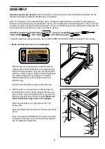
Страница 5: ...sure that the power cord is unplugged With the help of a second person carefully raise the Uprights 69 until the treadmill is in the position shown Insert one of the Extension Legs 63 into the treadmi...

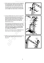
Страница 6: ...ed Bolt but do not tighten the other Bolt yet Attach the Left Handrail not shown as described above Note There is not a wire harness on the left side 5 Attach the end of the ground wire to the small h...

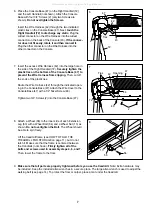
Страница 7: ...el Nut 13 as shown Do not overtighten the Bolt The Wheel should be able to spin freely Lift the treadmill frame see HOW TO FOLD THE TREADMILL FOR STORAGE on page 11 but do not latch it Make sure that...

Страница 8: ...resistance for electric current to reduce the risk of elec tric shock This product is equipped with a cord having an equipment grounding conductor and a grounding plug Plug the power cord into a surg...

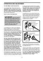
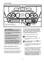
Страница 9: ...ils and begin walking As you exercise change the speed of the walking belt as desired by pressing the Speed buttons Each time a button is pressed the speed setting will change by 0 1 mph if a button i...

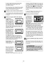
Страница 10: ...for a moment An E for English miles or an M for metric kilometers will appear in the Fat Calories Calories Pulse dis play Press the Speed button to change the unit of measurement When the desired unit...

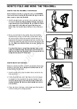
Страница 11: ...t the latch pin into the hole Make sure that the frame is securely held by the latch pin To protect the floor or carpet from damage place a mat under the treadmill Keep the treadmill out of direct sun...

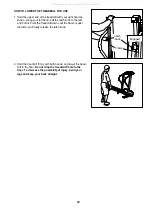
Страница 12: ...ot the treadmill down until the frame is past the latch pin Slowly release the latch knob 2 Hold the treadmill firmly with both hands and lower the tread mill to the floor Do not drop the treadmill fr...

Страница 13: ...wer turns off during use SOLUTION a Check the circuit breaker located on the treadmill frame near the power cord see the drawing above If the circuit breaker has tripped wait for five minutes and then...

Страница 14: ...n walked on SOLUTION a If the walking belt is off center first remove the key and UNPLUG THE POWER CORD If the walking belt has shifted to the left use the allen wrench to turn the left rear roller bo...

Страница 15: ...our exercise must be aerobic Aerobic exercise is activity that requires large amounts of oxygen for prolonged periods of time This increases the demand on the heart to pump blood to the muscles and on...

Страница 16: ...r attributable to freight damage abuse mis use improper or abnormal usage or repairs not provided by an ICON authorized service center prod ucts used for commercial or rental purposes or products used...

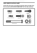
Страница 17: ...heel Bolt 64 2 1 Bolt 37 6 Wheel Nut 13 2 3 4 Tek Screw 58 8 Remove this chart and use it to identify small parts during assembly Save this chart and the EXPLODED DRAWING PART LIST for future referenc...

Страница 18: ...r Bolt 54 2 Clevis Pin 55 2 Cotter Pin 56 2 Ground Screw 57 4 Base Pad 58 11 3 4 Tek Screw 59 1 Controller 60 1 Lift Frame 61 2 Extension Leg Assembly 62 2 Warning Decal 63 2 Extension Leg 64 2 3 1 2...

Страница 19: ...85 84 77 83 82 78 77 79 80 61 58 63 64 66 57 58 65 61 62 13 69 58 55 54 55 54 13 53 57 58 71 72 37 37 76 76 73 73 58 57 51 53 13 37 38 39 37 38 37 38 39 37 38 40 2 57 58 62 63 64 13 66 50 56 90 88 89...

Отзывы: